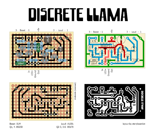
Some audiophiles have really gotten into preamps that use discrete opamp—basically using and bunch of individual transistors that make up the internal circuit in an IC. This trend has also made it's way into the guitar world as well. One of the simpler circuits I've seen you can do this with is the Way Huge Red Llama. Inside the CD4049 in your typical Red Llama is essentially a bunch of MOSFETs. John from Electronic Audio Experiments and Alec from Mask Audio Electronics worked on this and Alec sent me the schematic to share with all of you.
This is a library of perfboard and single-sided PCB effect layouts for guitar and bass. I'm not an electrical engineer by any stretch of the imagination, just a DIY'er who likes drawing layouts. It is meant for the hobbyist (so commercial use of any of these layout is not allowed without permission) and as a way to give back to the online DIY community.
Thursday, January 3, 2019
Discrete Llama
Happy New Year, everyone!
Some audiophiles have really gotten into preamps that use discrete opamp—basically using and bunch of individual transistors that make up the internal circuit in an IC. This trend has also made it's way into the guitar world as well. One of the simpler circuits I've seen you can do this with is the Way Huge Red Llama. Inside the CD4049 in your typical Red Llama is essentially a bunch of MOSFETs. John from Electronic Audio Experiments and Alec from Mask Audio Electronics worked on this and Alec sent me the schematic to share with all of you.
Some audiophiles have really gotten into preamps that use discrete opamp—basically using and bunch of individual transistors that make up the internal circuit in an IC. This trend has also made it's way into the guitar world as well. One of the simpler circuits I've seen you can do this with is the Way Huge Red Llama. Inside the CD4049 in your typical Red Llama is essentially a bunch of MOSFETs. John from Electronic Audio Experiments and Alec from Mask Audio Electronics worked on this and Alec sent me the schematic to share with all of you.
Subscribe to:
Post Comments (Atom)


I literally just finished building the other Red Llama last week, lol. Maybe I'll take a stab at this one too.
ReplyDeleteHappy New Year, :-) Great layout thank you...
ReplyDeleteInteresting. I didn't built a llama yet, so maybe I'll give this one a try.
ReplyDeletecan i have layout pdf please?
ReplyDeleteIt's in the Way Huge folder in the Dropbox.
DeleteThis is top or bottom? I must mirror print? Thanks for your support
DeleteIt's a mirror. Like you're looking through the top of the board. You don't have to do anything to the image if you're using the toner transfer method.
Deleteсечас как соберу)))))
ReplyDeletei built it but i get no sound at all.
ReplyDeletethe transistor go very hot
ReplyDeleteJust got this built, and managed to get it working with a slight modification.
ReplyDeleteBuilt as-is, it draws more than an amp of current, almost instantly heating the FETs to painfully hot and smelly. Surprisingly, it DOES pass sound in this state, but its very hissy and broken sounding (in the few seconds I left it plugged in, anyway).
So I added a resistor to the power rail (before the 1N5817). The Red Llama uses a 1k resistor there, so I did the same. Draws about 5mA of current and works just fine, if perhaps with a bit less gain than a standard llama. Could probably drop as low as 330ohm up there to pump a little more voltage into the circuit, but wouldn't go much lower with 1/4W resistors.
Also experimented with adding a protection zener to the first inverters MOSFETs. On my breadboard the diodes seemed to make the tone a bit more wooly, but still playing around with it (could be a capacitance issue, dunno for sure).
Thanks for the build report!
DeletePer Somnif's findings, I've updated the layout above. Changed polarity protection methods, replacing the 1N5817 in the first layout with a 1k resistors and adding a 1N4001 from voltage to ground.
I have simulated the mosfet stage (BS250-BS170) with LTSPICE and it generates a beautiful symmetrical soft clipped signal. but the problem is that the currents in both transistors are huge (12A). If I add a resistor to the power rail, it reduces the current, but it also changes the waveform a lot.
ReplyDelete