
Here's my take on the ZVex Fuzz Factory. The originals have the pots mounted to the board as well, but ZVex uses the little square pots which are more expensive. I wanted a layout that used regular 16mm pots, which are easier to come by and what you probably already have in your parts stash. Q2-3 originally were AC128s, but any PNP germaniums should work fine. I believe ZVex has used a variety of different germaniums over the years. Hfe ranges should be around 70-100 and 100-150 respectively (much like a Fuzz Face).

For what it's worth, most of my layouts with onboard pots are meant to be mounted from the solder side of the board, like this:

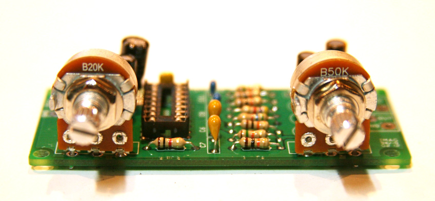
This way, the board will be vertical inside the enclosure, and the controls will be aligned like the original:
the gate and comp knob dont work really great at min position
ReplyDeletesee my FF on https://www.youtube.com/watch?v=Lb_49t0Sn2k
ReplyDeleteMine works!
ReplyDeleteI once had the Vexter series and it seems very similar.
Thanks!
It can add a led the project? How make?
ReplyDeleteSee the General Layout Notes tab at the top of the page. It has a diagram for off board wiring, including LED.
DeleteThe perf was wrong. It's been updated. Thanks for catching that.
ReplyDeleteGreat work,Thank you man.Works like a charm.
ReplyDeleteHello!
ReplyDeleteI gathered yesterday, very cool work. But it seems to me that the handle "comp", works in the opposite direction is not like all the knobs. Perhaps such a problem???
This comment has been removed by the author.
ReplyDeleteis there any replace for the acl128
ReplyDeleteThis comment has been removed by the author.
ReplyDeleteHFE ranges should be around 70-100 and 100-150, respectively corresponding to each value transistor, ie 70-100 is for Q2 or Q3,
ReplyDeletePardon my ignorance, thanks in advance
No worries. Yes, 70-100 for Q2, 100-150 for Q3
DeleteWhat if they arent?
DeleteI do have few ac128 but i know its hfe range
Will it matter?
I'll try with 2N3906 or BC557
ReplyDeleteWhat is the "CBE" and "EBC"? This is my first pedal and I'm having a hard time reading all of this.
ReplyDeleteTransistor pinout: Emitter, Collector, Base.
DeleteYou have to be very careful with that.
What does that mean exactly?
DeleteThose are the correct position on which need to work the transistor in the circuit.
Deletehttp://lmgtfy.com/?q=Transistors+pinout
http://lmgtfy.com/?q=How+transistors+work
:-D
Lol thanks!
DeleteOne last question; what size enclosure are you using?
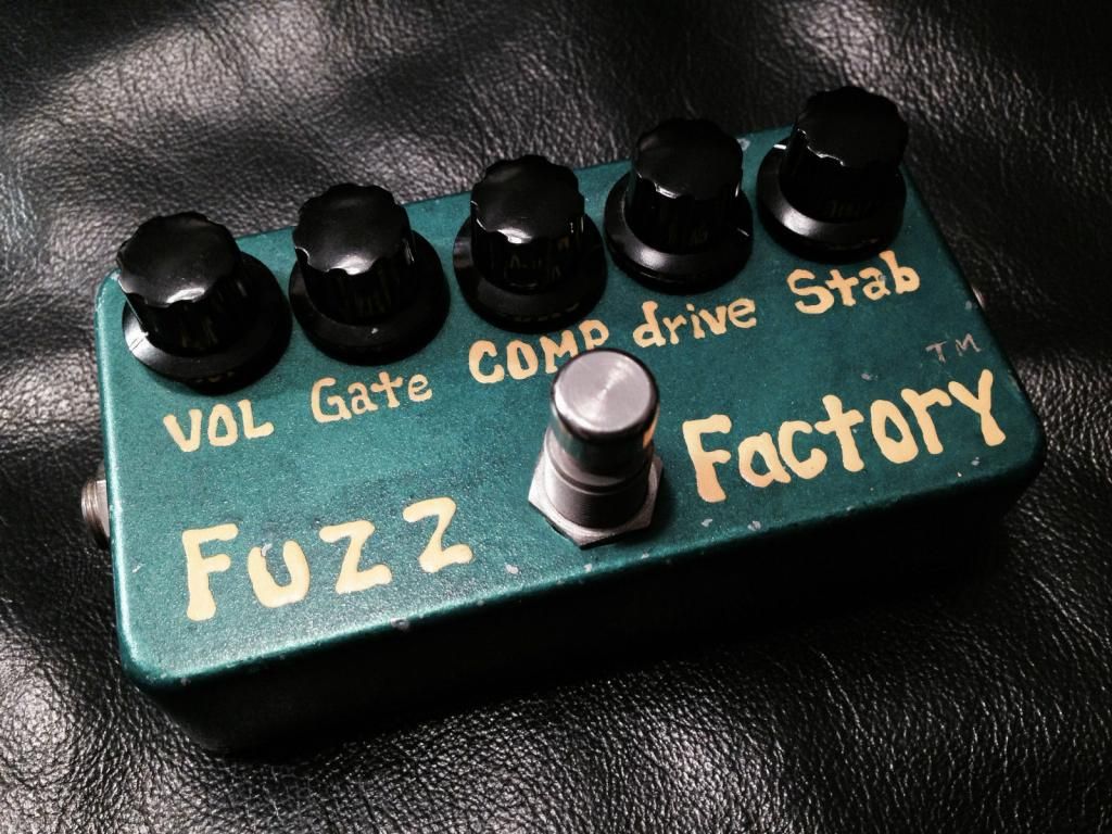
For the traditional FF, 125B or 1590B can fits.
DeleteI prefer 1590BB with upper jacks.
Any Silicon equivalent for ac128?
ReplyDeleteYou could experiment with some low gain PNPs, but really you want germanium PNPs in Q2-3. Doesn't have to be AC128s.
DeleteGreat! Thanks for the advise.
DeleteI'll search one of those for Q3.
I've already build it: tried with 2n3906 and bc557, but the knobs didn't worked correctly.
They mute the signal in some point, and it's hard not to oscillate or get "velcro" fuzz.
What can be the problem? Maybe the transistors voltage?
The problem is probably still your transistors. Q2 and Q3 need to be germanium.
DeleteThanks!
DeleteI'll change for the germanium ones.
Update!
DeleteUsed a 2sb54 pair, and the things going better.
But I have a lot o questions about Gate, Comp and Stab pots.
I have the strange feeling that I soldered them backwards, or at least if I listen the demos on yt
Comp knob all the way up (CW) is connecting, and CCW is 10k in between?
really thanks for the project! just a stupid question maybe. but the pots are seen from above or below? for example volume pot ground is 3? as you write on the general notes?
ReplyDeleteAll layouts on the blog with pot visible in the layout are if you're looking at them from below. Lug 1 of the Volume pot is going to ground.
Deleteperfect, I put all of them in the wrong way! :) thanks a lot for quick answer!!
Deletehey i make this ff and it works fine but i have a massive drop volume the guitar sounds higher when is on by pass, what could it be ?
ReplyDeletedo i need to change any pot or something?
i am using pnp germanium transistors
thanks.... I love your site
Sounds like something's wrong with your bypass switching. What method of bypass are you using?
Deletethe one on this site, but i have tested without the bypass switch and i tested on a protoboard and still a have the massive drop volume
Deletewhat colud it be?
Do you get the same volume drop with a different effect on your protoboard?
DeleteHi,
ReplyDeleteFirst of all I have to say that your blog is really impressive. Lots of infos thank you very much!
I am currently working on a FF circuit board. Everything was going smooth and then I discovered your blog. I am a bit confused now. Your layout is different from the one I use. http://frankyfuzzfire.free.fr/DIY/Fuzz%20Factory/Tutorial%20de%20la%20Fuzz%20Fire%20Factory.pdf Despite that it is in French, I realized that the connections for the pots are different on this layout and there is no "1N 4001 Diode" neither the "47uF capacitor" between the 9v and the ground.
Because this is my first build and I don't know much about electronics I would like your opinion if you don't mind.
Sorry to bother you with this.
Regards,
Mathieu.
The diode and cap you're referring to are for polarity protection and power filtering respectively. They're not always present in some originals, but a good practice for pretty much all builds (unless you're going to be powering the pedal only with a battery). As for the pot connections, some may be backwards, but with a noise maker fuzz like this one, that's not going to be that significant.
DeleteThank you very much for your answer. Yes I am going to use only batteries. The reason is, the effect will be inside of the guitar. I will use my layout first to see how it goes and change to yours if there is problems on the way.
DeleteOnce again thank you!
In the Zvex Factory image transfer documentation the width is stated as 1.3".... Should that be 3.3" ?
ReplyDeletemore like 3.7"
DeleteOh yeah. That's funny. I updated the file. It should be 3.8"
DeleteHi :). I'm planning to build this pedale because I'm looking for a classic Matt Bellamy sound. There is a point that isn't so much clear for me: it's about capacitors. I see that you have used only one ceramic capacitor (100 nf) and the others all are electrolitic. What about the polarization which is not specified?
ReplyDeleteAnd, more generally, which are the differences in performances between electrolitic and ceramic capacitors? It's just a question of dimension (ceramics are smaller in terms of capacitance than electrolitic)? Thank you so much for your time :)..
Polarization is specified by a minus sign on the electrolytics. You have to look more carefully on the pcb layout, but you should be able to easily tell the negative side on the perf layout. The 100n cap is actually film, though you can use a ceramic as well. Ceramic and film caps are generally used for lower values (1µ and lower) and electrolytics for higher values.
DeleteOk, thank you very much for your complete response. I will simply plug the minus sign on the low voltage available, it's correct? And, in general, I can use a ceramic or electrolitic capacitor at the same capacitance value without any change of result? Thank you for your patience.. :)
DeleteCorrect, though ceramics seem to have wider tolerances than electros. I had a few 4.7µ ceramic caps that I measured that were actually a lot lower in value (closer to 3µ), whereas electros seem to be more consistent. YMMV
DeleteThank you so much, all clear. I'll put in practice your advices as soon as I can for build this awesome pedal :)..
DeleteThis comment has been removed by the author.
ReplyDeleteJust finshed this awesome little monster.
ReplyDeleteThanks for all your work!
Do you happen to have the drilling template?
I don't. Though the pots are 0.8 inches apart and all in a straight line, so it shouldn't be too hard to drill.
DeleteHi. I have done this project and I have just compared it with an original Zvex vexter one. It seems that the volume pot is ok but for sure the comp and stab knobs works in opposite direction as the original one. Any idea why? I have followed all the steps.
ReplyDeleteSeems the schematic I based this on was wrong. It's been updated.
DeleteDo you still have photos of the old version? Because I made the pcb two years ago and I waited to this day with the completion of the project. I do not mind the reverse action of the knobs. Greetings.
DeletePart placement didn't change any, just the traces. So if you populate the old board as you see above it should still be fine.
DeleteThanks a lot!
DeleteBonjour.
ReplyDeleteIl.y a t'il un problème sur les traces u circuit. Notament au niveau du potentiomètre Strab arrivée +9v ?
Hello, I've just made this and all i'm getting is oscillation with no guitar signal. I've double checked the component placement, the soldering and I've checked for shorts and it all seems ok. Any idea what could be wrong?
ReplyDeleteNever mind, i missed a link on the foot switch.
DeleteThis comment has been removed by the author.
ReplyDeleteDoes it fit in 1590B or what kind of box u recommend?
ReplyDeleteI tried to build it in a 1590B, the build succeed but I couldn't get a battery inside so i changed to a 1590BB.
Deleteok thanks, i don`t need a battery so i can use the 1590B
DeleteHi everyone!!
ReplyDeleteCould I use transistors BC1088 replaced the AC128? Thanks so much!!!
No as the BC108 is an NPN transistor. A low gain PNP silicon might work like a 2N2907, but the circuit is designed for PNP germaniums, so YMMV.
DeleteIt works, the drawing is good. I built a few pedals from the drawings here. Thanks for them.
ReplyDeleteThere is the difference how Stab is connected on pcb and perf. Which way is correct?
ReplyDeleteI have transistors:
ReplyDelete2SA103--86,47,and 105 hfe
2N404---76,73 hfe
which should i use for Q2 and Q3?
thank
Use sockets and experiment with the combinations, but I'd start with either the 76 hfe 2N404 or the 86 hfe 2SA103 for Q2 and the 105 hfe 2SA103 for Q3.
DeleteOK thank you !!
DeleteThis comment has been removed by the author.
ReplyDeleteHow i know the correct side for the resistor? positive and negative
ReplyDeletesorry, i'm talking about capacitor not resistor
DeleteThe small grey mark in the image indicates the negative side
DeleteI see the grey mark o the diode but what about the polarity on the 47uF and the 10 uF capacitors, I don't see a grey mark for them :(
DeleteLook again ))) Capacitor is dark grey and polarity segment is light grey.
Deletewhat font did you use for the fuzz factory logo?
ReplyDeleteIs it just me or this layout has volume in left?
ReplyDeleteOriginal has vol i left.
Are potentiometers in reverse order?
I have a problem.
ReplyDeleteI didn't hear any sound, and the COMP pot burned. I saw a red dot appear on it.
Do you have any ideas ?
Verificado con transistores 1t308b
ReplyDeleteThanks for the schematic. It's a really cool pedal. I installed transistors from 1971, and it sounds great without any noise or whistle.
ReplyDeleteQ2 = GT308V (hFE 76, leakage 28 µA)
Q3 = GT308V (hFE 78, leakage 27 µA)
Replaced with others, sounds wilder and more interesting.
DeleteGT402ZH - hfe 72.5 (leak 174.51)
GT402G - hfe 148.9 (leak 269.48)
Are the Gate potentiometer terminals reversed? It's definitely working the other way.
ReplyDeleteI checked it in GPT, and it said the same thing without my prompting. Otherwise, everything seems to be working as it should.