
Here's a compact layout:

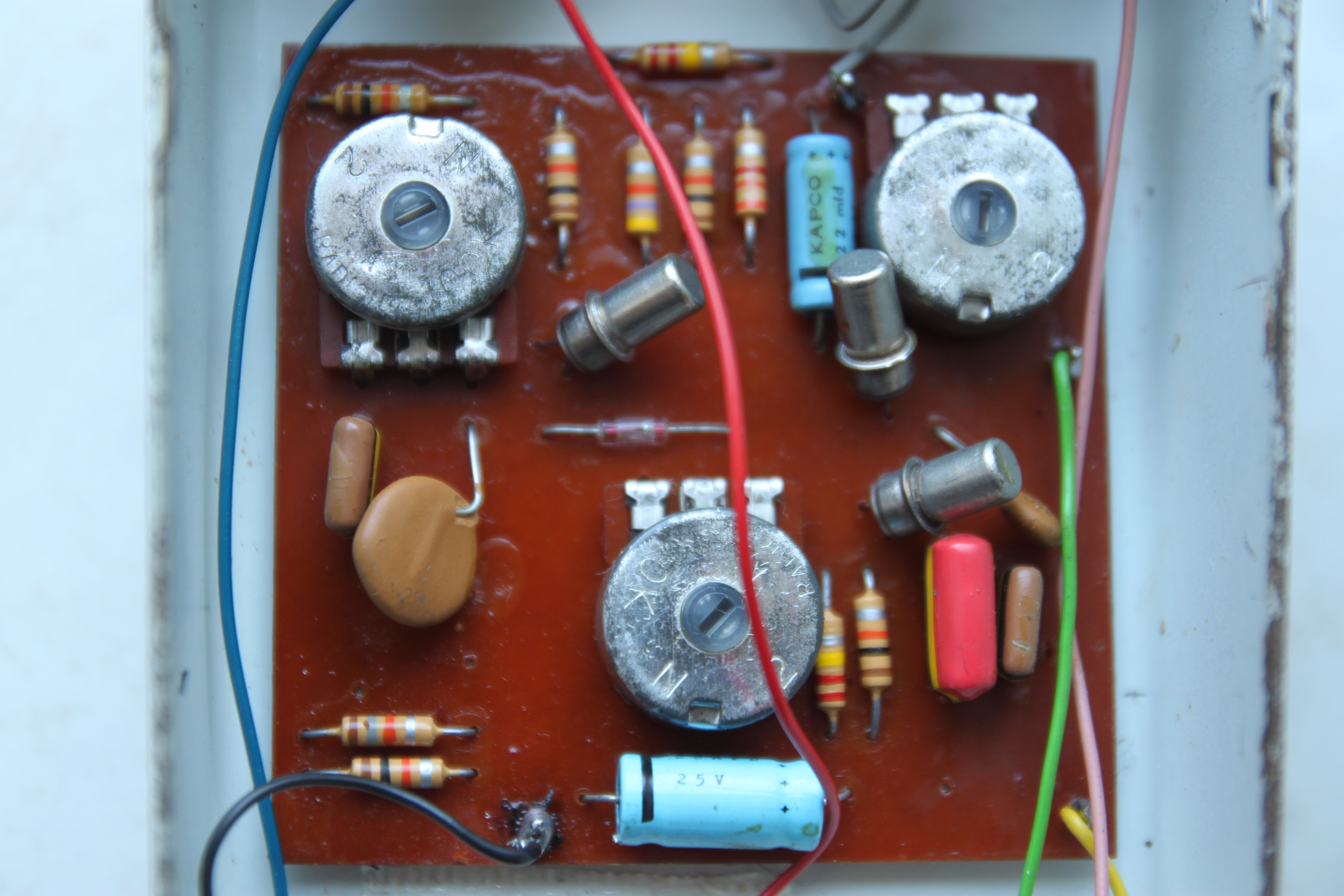
The original TB3 had a cool way of mounting the pots to the circuit board (see pic below). This approach was later emulated by Ross with their Distortion, Compressor, and Phaser pedals, and ProCo with the RAT.
Since I'm a sucker for eliminated offboard wiring, I created another layout (PCB only, sorry) inspired by the original, but updated for more modern components (like radial electrolytic caps and 16mm pots) and to fit in a 1590B or 125B.

And a shot with the components not in "outline" mode.

This has an optional 1M resistor between the base and collector of Q3 if using silicon transistors.
This layout can also be used for the Vox ToneBender Mk. III and the 3-knob Park Fuzz. See Fuzz Central for component changes.
That old-school-looking layout is bonkers! Just beautiful...
ReplyDeleteJust a question for the old school layout:
ReplyDeleteif i want to use npn transistor and -9v power supply, i only need to put polarized components (in this case diodes and electros) upside down, right?
Hope to verify this soon, it will be my first etch!
pardon, i was meaning PNP trannies, sorry for the typo
DeleteYeah if using PNP trannies, just rotate any polarized components. Good luck!
DeleteHi! nice old-school layout! Can i use two AC187 for Darlington pair and one AC188 for the fuzz?
ReplyDeleteThe AC187 is a NPN while the 188 is a PNP. So to answer your question no, not without some modification. Better to use another NPN for Q3. Sockets are your friends here.
DeleteWhy is there an extra diode added to the circuit? I think it wasn't in the original tone benders. Also the 2M and 1M resistors, what are they for? Just curious :) Great job
ReplyDeleteThe extra diode is for polarity protection, the 2M resistor is a pull down resistor so you don't get switch pops when activated, and the 1M resistor there if you're using silicon transistors.
DeleteIf I wanna use pnp germanium should I use the extra diode anyway? I know every polarized component and the power wires must be inverted, right?
DeleteI would use the diode. Always good to have polarity protection. And yes, if using PNP, flip the polarized caps, diodes, and power wires.
DeleteHello I think the 1n34 Diode can't be inverted in any case becouse it put the base of q3 to the ground......
DeleteI'll use 2n3904/bc548 for darlington formation, and germanium for Q3.
ReplyDeleteThis last one, and the diode, are the "must be"
The reason Q1-2 are in a darlington is because they didn't have transistors with a high enough hFE to just use one back then. Combining 2 modern silicon transistors will likely provide way too high a hFE and won't work. If you don't want to use low hFE germaniums for Q1-2, I suggest not trying to build this layout. Look at something like the DAM GB-83 or EQD Hoof Reaper.
DeleteThis comment has been removed by the author.
DeleteSorry if I insist on silicon transistors on all projects.
DeleteIt's not that I do not want to use them: where I live, germanium transistors are very hard to find and expensive (avoiding purchase on ebay, pay customs).
Thanks again!
No worries. I get that. Germaniums can be a pain to work with in the first place and often substituting silicon transistors makes it a bigger pain.
DeleteWhat's the correct size to print it? Do you have an image file with the correct size?
ReplyDeletehttps://www.dropbox.com/sh/iaegm30zvqgcvp1/AAD0x_GB3EZqRwcwSxW7QBlFa?dl=0
DeleteAll the files are in .pdf with correct size.
can you give a recommendation on what trannies to use? cheapest and easily obtained if possible. I get confused with all the different combos and names. Also is this a negative ground(boss style) or positive ground powered effect. I think i got that right. Id like to be able to use with my visual sound 1 spot, i know there are adapters but id rather avoid that if possible. Im a sucker as well for elimination of offboard wiring as much as possible. Also old school style layouts. Too bad the inverted pin type pots arent anywhere close to accessable as the 16mm right angle ones. i know small bear has them. havent checked the cost , but havent seen any layouts that would even accomidate them. Thanks if you can give tranny recommendations.
ReplyDeleteCheapest are probably Russian old stock germaniums like MP38s. That's what I'd start with for this build. I also cannot recommend enough getting something to test transistor gain (hFE). A lot of digital multimeters have them. Ideally you want the first 2 transistors to be pretty low (80 or lower) as they form a darlington transistor pair. The 3rd transistor should be around 100-120. Really, it's more about the hFE of the transistors than the actual type. Surf ebay and find some cheap options and measure. Or order from someplace like Small Bear that sells measure sets of transistors for various old germanium circuits. Best of luck!
DeleteWhich is the difference on the cap from Q2's emitter to ground? Lower value = more gain/highs?
ReplyDeleteYeah I think that's right.
DeleteAm I blind or stupid? Unfortunately I can't find the transfer image for the original inspired layout. Can you please help me and point me to that? Thanks in advance!
ReplyDeleteIt's in the Colorsound_Solasound folder:
Deletehttps://www.dropbox.com/s/scai2tjcp4xjn4n/SolaSound%20Tonebender%20Mk3.pdf?dl=0
ReplyDeletesomeone verified? I have built it and I have voltage in the circuit of 0.82v. any ideas maybe polarity control wrong
Lug 2 from volume goes straight to the switch??!
ReplyDeleteWhat is the function of the GE diode in this circuit?
ReplyDeleteGermanium transistors can be pretty sensitive to temperature changes and the diode there helps to prevent temperature from un-biasing Q3. From Coda Effects' explanation:
Delete"When the temperature changes, the characteristics of the diodes change the same way the characteristics of the Q3 transistor, and avoid biasing problem by flowing the excessive current to ground."
Obrigado
DeleteThis comment has been removed by the author.
ReplyDeleteVintage Layout: Verified
ReplyDeleteBUT the reverse polarity protection diode (1N4001) needs to be turned around otherwise it won't work.
The Vintage Layout is just beautiful. I just used normal pots, turned the lugs with a plier and soldered the connections with short wires.
I built it with Vox specifications and it rips like it should be. Thank you so much for this layout! :-)
This comment has been removed by the author.
ReplyDelete