

Monday, October 3, 2016
EchoPlex Preamp
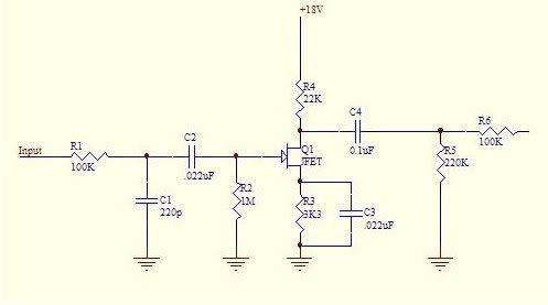
The EchoPlex Preamp emulates the input stage on the old EchoPlex EP-3. It provides up to 11dB of gain and is mostly used as an always on pedal to sweeten the user's tone. If you want to add the volume control, use a 500k pot and connect lug 1 at the junction of the 100n cap, 220k and 100k resistors, and run lug 2 to ground. This also works really well when running at 18v. Schematic for reference can be found here.

Subscribe to:
Post Comments (Atom)
Hi! The volume control with 500k pot in your comment means GAIN of the product version?
ReplyDeleteI would think so.
DeleteThanks. I'll build it with 18v this week.
DeleteA/B/C 500k?
DeleteA/B/C 500k?
DeleteI have the same doubt about the pot. A/B/C 500k???? Thanks a lot
DeleteI'd go with B personally.
DeleteHo trovato dei vecchi Matushita k66 (2sk?) (Fet x audio stage bf) Vanno benissimo,funzionano anche con una tensione di drain di 2/3v vanno benissimo sia con 9v o con 18v, non si nota alcuna differenza significativa,teanne una lieve distorsione a 18v.
DeleteLa cosa che ho trovato di eccellente in questi k66, è l'incredibile ricchezza di armoniche!!. X il controllo del volume ho messo in parallelo alla resistenza in uscita da 100k un potenziometro da 220k lin. Non chiude completamente e ha un'ottima escursione.
this will work with j201 ??
ReplyDeleteProbably. Though you may need to adjust the value of the 22k resistor
DeleteI've made one using J201 and worked fine. Yes, 22k needed to be adjusted. Question, if I want to use a trimpot, how should I connect it?
DeleteJust jumper lugs 1-2 of the trimmer, then connect lug 3 to the voltage and lugs 1-2 to the other pad from the 22k resistors.
DeleteI built a few ones, I used J201 in the last one.
DeleteI adjust the 3k3 too for more output, 1k5.
Which is the recomended voltage to get adjusting 22k?
Thanks
Why isn't the underside mirrored like the rest of your layouts?
ReplyDeleteUm... cuz I forgot to do it. :D Fixed now
DeleteI started soldering this together then realized it :(
DeleteHello, first congratulate you on your work is really incredible, I subscribed to your youtube channel; ).
ReplyDeleteDo you think it is feasible that you can make a layout of the multiplexer echo machine? (1776 effects).
It would be amazing.
Best regards
JP
verified. I just made it on perf board. Really puts a nice sparkle to the tone.
ReplyDeleteThanks for another great layout
Hi
ReplyDeleteWhat would be the best bias on this one? 4,5v or could I get more volume by increasing the voltage? Thanx for the great layouts
4.5v is probably best. Increasing that probably won't give you more volume, at least without increasing noise or altering the tone. If you want more headroom, use an +18v supply
DeleteIf I have the bias set on 4.5v at 9vdc, then I should double that value at 18vdc, is that right?
DeleteIf yes, then In miss the point... What is the difference between having a higher bias at 9vdc and being already higher at 18vdc? Can I just alter the r22k at 9vdc instead of going to 18vdc?
If you increase the voltage to Drain, the voltage to Source will increase too, and the working headroom will be higher (less compression/distortion).
DeleteThe resistor to Drain (voltage to jfet) is setted to have the 50% of the overal voltage input: not 9v strictly.
Think in the 22k resistor like an X in a equation: if you move that resistor, the overall functioning will change.
DeleteThe 50% I've mentioned, is the "recomended" area to work in this circuit to avoid volume loss, or in another extreme: saturate.
Thanks a lot for your prompt reply! I understand and I agree with what you said.
DeleteI wanted to know, if the voltage to Drain that you would get at 18vdc can be set to be the same when using 9vdc by simply adjusting the 22k resistor?
If yes, then what the point of using necessary 18v?
This comment has been removed by the author.
DeleteYou're welcome! :-)
DeleteNot exactly: you have to re-bias the resistor that goes from Source to ground.
This one is setted to avoid the "distortion" point: depends of each tipe of J-fet and/or design.
As I said... it's an equation: the J-fet is placed in between.
22k resistor is the value, that in conjunction with Rs (source resistor), made the Jfet work with ~50% of voltage.
Using 18v will made the Jfet work more "relaxed", more headroom (volume after compress).
How can I bias the transistor?? The V in D is 7.4
ReplyDeleteAdjust the value of the 22k resistor
DeleteThanks!! You're awesome!
DeleteThe voltage of D is 7.23 with a 22k resistor, I have to put a 63k resistor to have 4.5v in D, I discover, with 7.23v the booster are nice and clean and with 4.5v. The sound are fatter and a little harsh. Is nice in both ways!! Thanks man!! You're the best!!
Deletethe sound is really low, what should I do?
ReplyDeletethe diode 5817 can be replaced with 4007 or 4148 right?
I'll try with 4007; it's like 4001 with more wattage
Deletejust finished the perf version and the very first 2n5457 I pulled out of the tray fired right up! this is one of my favorite preamps.
ReplyDeleteall 20 or so Jfets worked the same for me - Vgs .8 volts
Deletenot a lot of db boost but sweet tone fattner similar to a good RM
Hi, im a real newbie here, is there any way you can upload the pcb with the volume control? Is it necessary for it to work with 18v?
ReplyDeleteHope it help :)
Deletehttp://i.imgur.com/JGnYaIW.png
maybe better solution https://drive.google.com/file/d/1kyHu9KBYZp77-FmmvNkJFokhkaTEVeb0/view?usp=sharing
Deleteand PCB layout change https://drive.google.com/file/d/1NvqCb-G-mK_iK-ll3buP3OBH-_pVeiE7/view?usp=sharing
DeleteThis comment has been removed by the author.
Deletethe change of resistance curve
Deletehttps://drive.google.com/file/d/1t1bRs2Lr7qCwef622D88ZRPimx1Xk_ed/view?usp=sharing
Hi, newbie here too, and it looks like an easy one to start with. I just have one question : how do I know what kind of capacitor I should use ? Is there a color code or something ?
ReplyDeleteThanks for your great work !
There's a numerical code on capacitors. Just google capacitor codes. If you're concerned about the type of capacitor (ceramic, film, etc) in my layouts green = film, yellow = ceramic, grey = box, and black = electrolytic. Best of luck!
DeleteThat's what I was looking for ! Thanks a lot !
DeleteFinally had the time to build it, sound awesome !
DeleteI built it with a B500K pot. Passed the quarter of its course, it has no much impact. Any idea why ?
Anyway, thank you for this blog. Up to the next build now !
I used 1n4007 instead of 5817.
ReplyDeleteIt's possible the 4007 lowers the volume due to voltage?
I wouldn't think the voltage drop would be that dramatic...
DeleteI have there a few 1n5819... should I change the 4007 for this one?
DeleteWhich is the difference with the 5817?
Thanks
The 5819 is in the same family as the 5817 (schottky diodes), but the 4007 will fine for this application too.
DeleteIs the same if I remove the 220k resistor, and put there a 1M pot as a variable resistor, for Master Volume?
ReplyDeleteAs I can notice, the 500k pot and 200k resistor are working in parallel to ground.
Am I correct?
No, the 500k pot and 200k resistor in parallel make the pot effectively 150k. Check out this calculator for parallel resistance:
Deletehttp://www.sengpielaudio.com/calculator-paralresist.htm
My bad...now I get it
DeleteSo, I'm doing the same if I remove the 220k resistor and put there 250k pot as variable resistor?
Newbie here. What can I do to get more bass out of this?
ReplyDeleteTry increasing the value of the input capacitor (22nF right by the JFET). You can also play with the value of the output cap (100nF).
Deleteanother newbie here, first thanks for the blog and the work ,when you say the 500k pot connect lug 1 to junction and lug 2 to ground the 3rd lug is jumpered with 2nd?
ReplyDeleteIt can be, but doesn't have to be. It should work the same either way.
Deletety¡¡
ReplyDeleteHello and thank you for this wonderful website!
ReplyDeleteI have two questions, please:
1. What FET exactly do you recommend?
2. What is the real purpose of the diode and the 1000uF cap? Can I just adjust the 22k resistor instead, is it the same?
Best,
Y.
Hi there! My humble oppinion:
Delete1. I've built several times this one; always used BF245 and 2N5457. J201 need to be rebiasing here.
2. They're for reversed voltage protection. It's not the same to use that resistor.
Thank you very much for the prompt answer and help!
Delete1. Any experience with J202? Some swear on it saying it is the closest one to the original TIS58. I don´t have engineer´s degree, so I don´t know nothing about specs and stuff, sorry! :-(
2. I understand. My question was actually going about the meaning of author´s sentence "works really well running at 18v" and about the debate 9v/18v. If there is only one specific voltage range for the right operation of every FET, I can not see how it will work on both voltages? When it works right on 9v, you have to adjust the 22k resistor in order to reach the same range when using 18v, does that make sense?
For instance my build (w/ 2n5457) works good on 9v, but it is barely audible/ working when switching to 18v.
1: not J202, but yes J201. It need to be re-biased! The last time I did it, replaced 3k3 res (from Source to ground) for 1k5: with this value I kept 22k, and 4.5v to Drain. I kept 4.5v to drain because...(point 2)
Delete2: Drain voltage is for design. In this case, it works with 4.5v (from 9v), and almost 9v from 18v. You have to see the mentioned Source res (3k3 or 1k5) to keep the Jfet 'balanced'.
There's a looong way to understand it...a lot of equations and etc's.
I keep it simple... I don't know if it es therical correct; but by ear, sounds really good.
Less than that value, distort, and more than that value, reduce volume.
More Drain voltage (+ 4.5v) gives more headroom, that's why using with 18v can help.
Nothing works better than 5457's... but the closest one is BF245A.
Può andare bene lo stesso il bf245b? Grazie
DeleteSry for newbie question, but it works with 9v?
ReplyDeleteI believe so, yes.
DeleteI really like this little circuit but the solution that is given to the volume does not work very well.
ReplyDeleteI solved the problem in the following way, remove or not apply, for those who will do the circuit now, the resistance of 220k and use the holes to solder the wires that will connect to the pot of the volume, I used an A100K can also be used a B100k, and now finally the volume goes from 0% to 100%.
This comment has been removed by the author.
ReplyDelete
ReplyDeleteHi, I have a question, how about using 2SK117 in this scheme?
It's nice to be able to spend 15 minutes (not counting board etching) and end up with a real impact on my tone. I made a tiny mod to the pcb to enable board-mounting of the pot, which made it very easy to mount in my "franken-wah" at the start of my signal chain to strengthen my signal (yes, I do prefer wah before fuzz). I used to use a simple buffer, but find the boost from this preamp sweetens my overall tone through the rest of my effects chain. Thanks for the great work!
ReplyDeleteJuan which legs did you solder into ground and then the other side? Thnx:)
ReplyDeleteVerified!! I used 2sk152 transistor, and 1n4004 diode, and 330pf capacitor instead of 220..and I didn't need to biasing nothing for this replacement, so far I tried it just with 9V, pedal/tone is absolutely amazing, thank you so much for this :-)
ReplyDeleteCan I affect highs or tone in general if I change value of 220pf capacitor, for now I use 330pf..if not what can I do to do it, I wanna play a little bit with sound?
ReplyDeleteAnd one more thing, can I make reverb effect if I build and connect spring reverb tank to this circuit, output from this connect to input of tank, and output from tank to input of amp? Thx :-)
That 220pF cap is just barely rolling off some of the highs at the input. Changing the 22nF right next to the JFET and the 100nF cap will alter the tone the most.
DeleteI also realized that this 2sk152 works maximum at 15V,so I cannot try ot with 18V,but it's cool anyway..thank you
ReplyDeleteNewbie question, where to measure drain voltage? Against J-FET "D" lug and ground? I measure to much volts there 14,5V when powered with 16,5V.
ReplyDeleteWhat is the solution increase resistor 22K or 3K3?
I have all components the same as on the original layout, j-FET 2N5457
DeleteThe 22k is what you want to adjust. And you are measuring correctly.
DeleteJ201 work better IMHO,thanks from Brazil.
ReplyDeleteCan i use 2sk30 for transistor?
ReplyDeleteDoes it also work as a signal buffer?
ReplyDeleteIt was made as "signal buffer". That fixes output resistors leave it as unity gain (I would say +3/4db).
DeleteI've built mine as a "always on" box in a 1590A ;-)
I'm diving in DIY pedals, have done some elctronics in my studies but I'm a bit rusty and not an expert on the subject. How do you modify the gain on this circuit ?
ReplyDeleteI replaced the output series and parallel resistors with a 100k pot for simplicity. I get more volume and use less components. I recommend this over the other suggestion of where/how to incorporate a pot. I also experimented with different values on the resistor bypass cap value. Larger the cap the more grit this pedal can produce and at the range of boost as well.
ReplyDeleteThis is an awesome project! Curious if there will be any substantial difference if i omit the 220pf capacitor. Is leaving it out going to give me the same level of highs as the input? (i run my guitar and effects pretty dark as is)
ReplyDelete