This is a library of perfboard and single-sided PCB effect layouts for guitar and bass. I'm not an electrical engineer by any stretch of the imagination, just a DIY'er who likes drawing layouts. It is meant for the hobbyist (so commercial use of any of these layout is not allowed without permission) and as a way to give back to the online DIY community.
Showing posts with label SolaSound/ColorSound. Show all posts

Friday, February 4, 2022

Not A Muff

Happy Fuzz Friday, all! Recently I got a request for the new EQD Hizumitas. Found a schematic for it over on FSB and it's just a BMP. The values are tweaked, but the topology is the exact same as a standard Muff. If you've hung around here for really any length of time you know how many times I've laid out the BMP. There are so many clones out there dating back to the early 70s, most of which I haven't really explored here on the blog. So using Kit Rae's fantastic Big Muff site, I put together a BOM of 6 versions of non-muffs, including the Hizumitas and the Elk Sustainar the Hizumitas is derived from. So for your building and experimenting pleasure, here's the Not A Muff. (BOM, schematic and drilling templates linked below)


Also, if you're interested in how I laid out this board, I did a livestream over on YouTube. I've been trying to do a couple streams a month of just chilling and doing some layout work in Eagle. So go and sub and all that nonsense.

Friday, May 3, 2019

Royal Albert Hall Bender

Happy Fuzz Friday everyone! Got a request for this one put forth on FSB. It's based on the ThroBak sTone Bender, which itself is just a straight clone of the Tone Bender Mk II Professional. The layout is setup for positive ground and PNP transistors. You can use a voltage inverter daughter board or flip any polarized components and use NPN transistors if you want to daisy chain this with other effects. Also, I added a 1k limiting resistor of the bias pot (far upper right side of the board) that may need to be adjusted to taste. Easy fit in a 1590B.

Wednesday, August 30, 2017

Colorsound Tremolo

Haven't done a tremolo in a while, so let's remedy that with the original 4-transistor Colorsound Tremolo (the re-issue is the 3-transistor version). Originals used 2SC945 transistors (BCE pinout), but I've laid this out for more common NPN transistors with CBE pinout. You might want to use a C100k pot for the Speed control. Here's the schematic for reference.


Wednesday, April 5, 2017

What the Wah?

Hadn't done a wah in a while and thought I'd do project where you can build several old school wah circuits on the same board. Many of the early wahs back in the late 60s were based on the original Thomas Organ CryBaby, and as a result many of them follow the same topology with a few value changes. Here's the schematic:


A lot of the original transistors used have a BCE pinout, so I've made 2 layouts: one for BCE and one for the more common CBE pinouts. Generally speaking your just need transistors in the 300-400 hFE range, however with many circuits, different transistors offer different flavors. So as always, socket and experiment.


Friday, June 10, 2016

One-Knobber Project

I haven't made a detailed project in a while, so for Fuzz Friday here's the One-Knobber. It's based on the old Dr. Tony Balls stripboard layout that covered the ColorSound One-Knob, D*A*M Meathead and Dark Meathead, and a one-knob adaptation of the '66 Vox ToneBender, and I've added the Ritual fuzz by Black Arts Toneworks.


Friday, December 18, 2015

SolaSound ToneBender Mk III

For #FuzzFriday I give you the SolaSound ToneBender Mk III. The Mark III was a smoother and less aggressive follow up to the famous Mk II Professional. SolaSound built it for several other companies–Vox, RotoSound, Park, etc. There are plenty of layouts for this classic fuzz out there already (there's already 2 on this blog), but I drew this up for a 2-in-1 box I'm putting together (this into a Catalinbread RAH) and thought I'd share. So here's a modern layout for the ToneBender Mk III. Originals used PNP germanium transistors, so the perf side reflects positive ground layout, but the PCB side shows negative ground if you want to use NPN transistors. For more info on the circuit check out this page.


Here's the drilling template for it.

Tuesday, November 3, 2015

Colorsound 3-Knob ToneBender Reissue

I was trolling Google Images the other night looking for schematics and I stumbled across this. I think the only thing this reissue has in common with an original is the enclosure and graphics. It uses a single opamp with soft clipping and a Big Muff-style tone stack. If you use 9mm pots you could probably cram it into a 1590A.


Friday, September 11, 2015

ColorSound Bass Fuzz

Here is the ColorSound Bass Fuzz for today's #fuzzfriday post. It's pretty much an amputated Big Muff. It's been tuned for bass guitar and has the gain recovery stage removed (for simplicity I suppose... that and the BMP can be just excessively loud). The first gain stage also doesn't have the typical diodes a normal BMP has.


Wednesday, July 15, 2015

ColorSound Wah-Wah

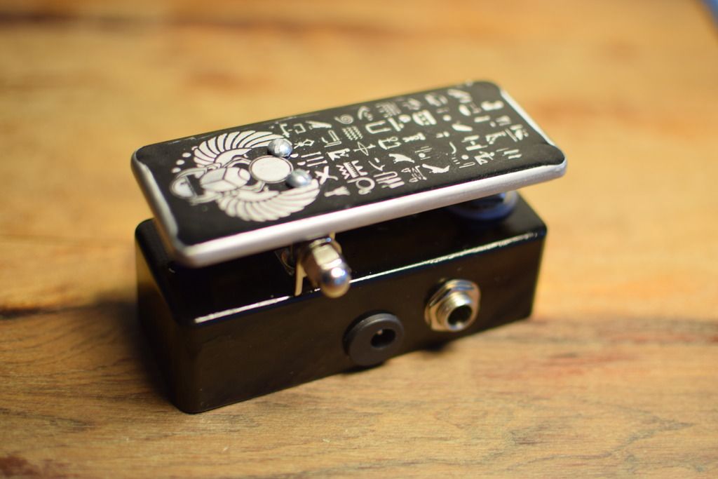
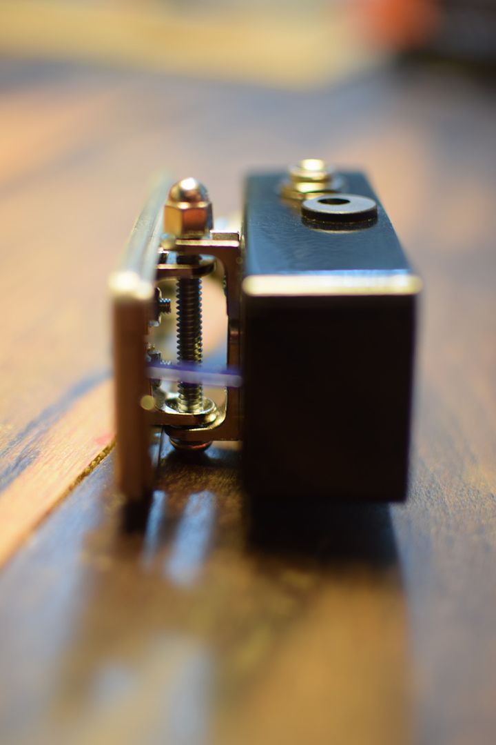
Here's the ColorSound Wah-Wah. I hadn't laid out a wah before, probably because I haven't built one myself before, and I don't use one much when I play. Anyway, the ColorSound Wah-Wah is pretty simple and sounds very good. What makes it unique is that it doesn't use an inductor like most wah circuits. This might be a good candidate to throw a buffer in front, but it's not necessary. There is a volume pot which you could omit if you want (in which case the Volume 3 pad becomes the output). You could also throw this in a 1590a if you wanted a non-treadle/fixed wah pedal. Or if you're really brave, you could mod a 1590a into a treadle pedal like Thomas Hafemann did.


Wednesday, April 1, 2015

ColorSound OverDriver

The OverDriver is a dynamic transparent drive that works great with a tube amp. It's essentially a massive clean booster that pushes the amp to overdriven tones. Original units from '69-'70 didn't have a master volume control, but modern versions do and it's a good addition to the circuit. (If for some reason you don't want the master volume, the Volume 3 pad becomes the Out pad.)

I've upped the power filter cap to 47µ and added polarity protection and a pulldown resistor. The original BC transistors used had BCE pinouts, but I've laid the effect out for the more common CBE pinout. Also, the BC169 transistors used for Q1 and 2 will probably be pretty difficult to source, so socket and try out some alternatives (2N3904, 2N5088, etc). Might be a tight squeeze horizontally, but it should fit in a 1590B enclosure.


Here's my build. Haven't boxed it up yet, but I tested it and it seems to work. I used 2N2222s for Q1-2 and a BC550 for Q3, though I plan to try out some different ones. Also, you may want to try a lower value for the gain pot. There's a serious drop in gain once you start turning it down. Since the first stage is based on the Fuzz Face, maybe try a B1 or 2k pot. Reverse log might not be a bad idea either.


Friday, February 6, 2015

1590A Tone Bender Mk.II

Here's the mighty SolaSound Tone Bender Mk.II shrunk down to fit in a 1590a. I laid it out for NPN transistor, as I really wouldn't want to try and squeeze a charge pump in a 1590a along side the effect board. Like the larger layout I posted last year, you could build the Marshall SupaFuzz with this layout as well. See that post for info on the value changes.


Update 3/22/15: I was trying to build this one to verify it and realized I'd forgotten the feedback resistor that goes from the base of Q2 to the emitter of Q3. The layout above is updated and should be fine now.

Saturday, November 15, 2014

SolaSound Tone Bender Mk. III

Smoother sounding than the Mk. II Professional, the Tone Bender Mk. III not only added a tone control, but the circuit was a deviation from earlier Tone Benders. Q1 and 2 create a Darlington pair that amplify the signal, while Q3 is what creates the fuzz. I've laid this out for negative ground operation, so make sure to use NPN transistors. Q1 and 2 can be low gain silicon if you don't want to use germaniums. Q3 could also be silicon, but a germanium is most likely going to sound best. You can also reduce the value of the 220k resistor (or just replace with a jumper) between Tone 2 and Volume 3 for more output.

Here's a compact layout:


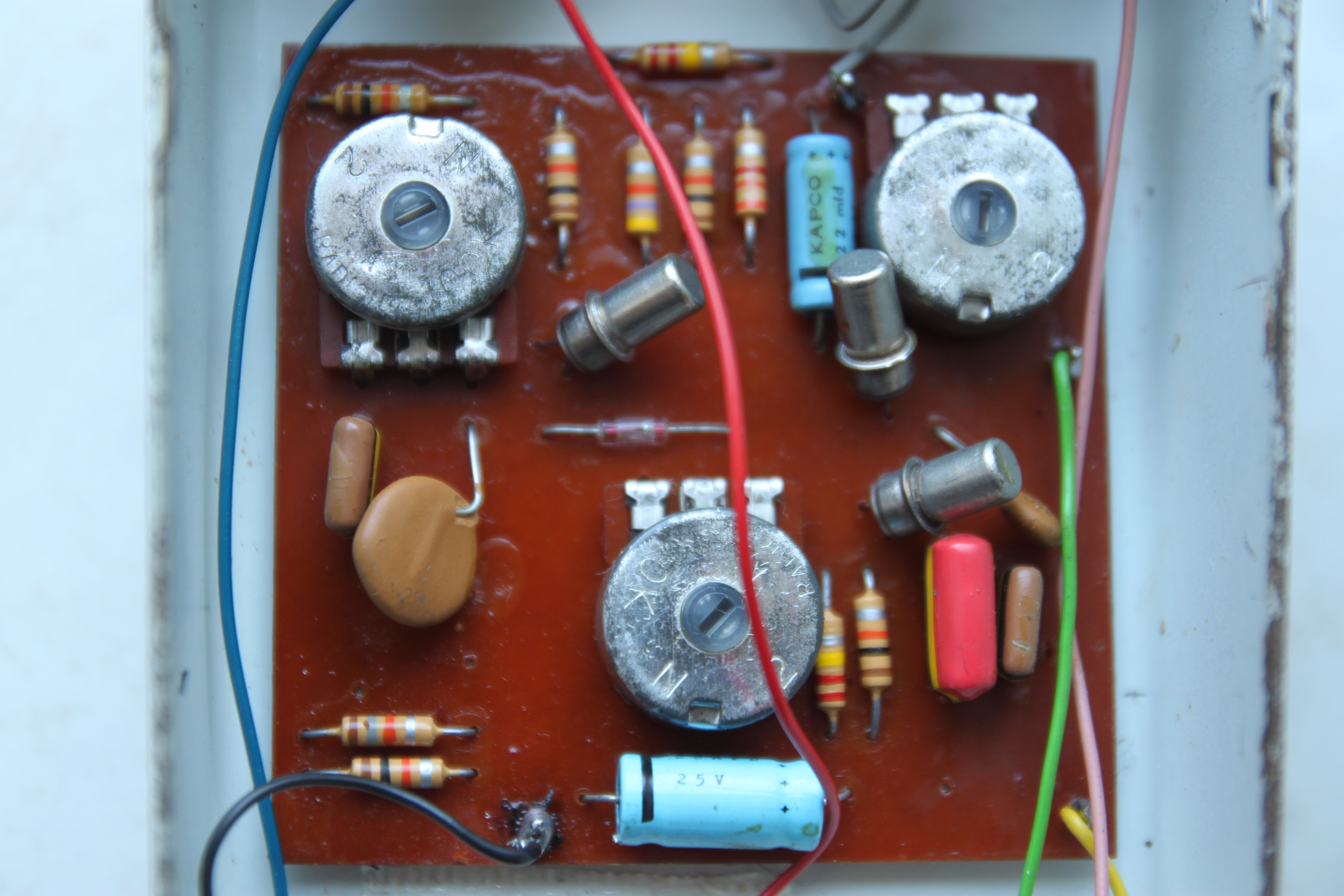
The original TB3 had a cool way of mounting the pots to the circuit board (see pic below). This approach was later emulated by Ross with their Distortion, Compressor, and Phaser pedals, and ProCo with the RAT. 


Since I'm a sucker for eliminated offboard wiring, I created another layout (PCB only, sorry) inspired by the original, but updated for more modern components (like radial electrolytic caps and 16mm pots) and to fit in a 1590B or 125B.


And a shot with the components not in "outline" mode.


This has an optional 1M resistor between the base and collector of Q3 if using silicon transistors.

This layout can also be used for the Vox ToneBender Mk. III and the 3-knob Park Fuzz. See Fuzz Central for component changes.


Monday, November 10, 2014

Sola Sound Tone Bender Mk. II Professional

Here's another layout with onboard pots. The Sola Sound Tone Bender Mk. II is probably most famous for shaping some (but not all) of the guitar sound of legendary guitarist Jimmy Page on Led Zeppelin I. Originally it was a positive ground effect, but I've laid it out to use NPN transistors. This way you can daisy chain it with normal negative ground effects, or avoid using a 9V battery or making a voltage inverter. I've added a polarity protection diode and a pulldown resistor at the input. I would also recommend as I did with the Fuzz Face, to swap the stock B1k pot controlling attack with either a C1k or B2k pot for better control.


The hfe of the transistors should be around 70 for Q1 and 2, and 100 for Q3 (according to Fuzz Central). I've personally had good luck with some Russian MP38a transistors. You can also build the Marshall Supa Fuzz with this layout by making the following substitutions:

  • Increase both 4.7µ capacitors to 10µ
  • Reduce the 100k resistor going from the base of Q1 to ground to 10k
  • Reduce the 100k resistor going from 9v to the collector of Q2 to 47k
You can also use this layout to make the original positive ground effect using PNP transistor by just inverting any polarized components (basically just flip around the 3 electrolytic caps and diode).