This is a library of perfboard and single-sided PCB effect layouts for guitar and bass. I'm not an electrical engineer by any stretch of the imagination, just a DIY'er who likes drawing layouts. It is meant for the hobbyist (so commercial use of any of these layout is not allowed without permission) and as a way to give back to the online DIY community.
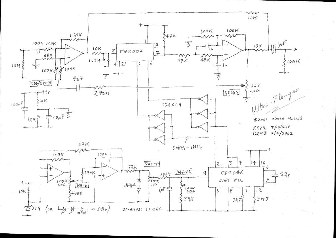
Got a request for a flanger effect, and hadn't seen many layouts for the John Hollis Ultra Flanger (that didn't have tiny thin traces anyway), so I thought I'd give it a go. For the record: flangers are hard. I knew from the get go this one wouldn't fit in a 1590B, but it will fit nicely in a 1590BB. There's empty space at the top corners you can cut into to fit around the screw posts in the corners of the enclosure if you need to. Here's the schematic and here's what John had to say about the circuit:
I was originally going to develop a minimum part count version of the EH Electric Mistress. Instead I went for a something with the versatility of an MXR flanger and the extra wide sweep that the A/DA flanger was known for. It needed an extra chip to get the wide sweep but it's worth it. Current consumption is very reasonable at around 2 to 8 milliamps dependent upon clock frequency.
Update Aug. 3, 2016:
Fixed the connections from the MN3007 to CD4049. Note jumper under CD4049.
ciao massimiliano,volevo chiederti tu hai gi realizzato questo pedale?a te funziona?io ho seguito tutto come dice la figura in alto ma non mi da l'effetto flanger,esce solo un suono pulito,potresti dirmi qualcosa in merito?grazie anche tramite wathshapp +393474943174 o email : gennyespo85@virgilio.it
I did it 3 times, two of them with new components and it does not work. The effect of the guitar comes out totally clean. They should corroborate before giving it as verified
Check you don't' have a bridge somewhere, run a knife through anything suspect the components are close as is the ground pane I have gotten a few pedals working that way .
Thank you for the layout, just finish it and it works. You can tag it as verified. I build the PCB version but sadly I etched it before you last correction so I had to add 2 jumpers under the CD4049. Thanks a lot for your work.
Excuse my English, but manufacture this effect and although you can hear the '' tick '', the guitar comes out totally clean. Can the problem be in the IC MN3007?
Hey there, thanks for providing such a great resource! I'm looking on Small Bear for the 4049 chip and there's 4049UBE and 4049BE options. Which one would be the right chip for this project? Cheers!
None of the documentation I've seen on this circuit specifies which one. You might want to grab one of each and socket that chip so you can test which one works best.
Sure, since it isn't a divider trimpot, it is just a variable resistor (lugs 2 and 3 are connected), you just have to find the right spot, but you only will work with like 1/3 of the total trimpot rotation, so it means less precision. But yes, you can.
According to the schematic, Manual 1 and Manual 2/3 should be changed for each other. The 39k resistor goes to Manual lugs 2/3 and the 1uF positive side capacitor goes to Manual Lug 1.
Hi! I just build this and I have the "clean sound" issue, could this be related to the problem? If so, shouldn't we ask Mark to make this correction? Thanks in advance!!
hi guys. I just finished assembling the components on the pcb as shown in the photo, but it does not work, only the clean sound of the guitar does not work. has any of you solved this problem? you tell me what should I do? thanks
hello good day, I have built this project, and I think it should not be marked as verified, I have all the correct values in capacitors, resistors and IC, and the pedal has not worked, I believe it should not be placed as verified as the not fucniona effect, I have looked for information in other forums and everyone has a different way to make it work, some change resitance, another recommend change in ic, but nobody agrees as to make it work, I hope that my recommendation is taken into account, I will work soon to try to make it work and leave the information so that now, it is a verified project
Hello, I have a other problem: when i turn knobs, i can hear the effect. But it doesn't Work "automatically". I've changed the CD4046 and the CD4049, and it still have the problem. I've checked all my componants and all my wire, it's all good. Does somebody have the same problem ? Thank for your answer.
I built this layout and it works. Thank you Effects Layouts!
Before putting it on the PCB, I built most of it on a breadboard using the Geofex schematic (http://www.geofex.com/PCB_layouts/Layouts/ultrafln.pdf) -- note that this PCB does not include all of the power supply filtering shown in the "improved Ultra Flanger" version from Geofex -- which is unfortunate.
I used a TL062 for the LFO and a TL072 for the audio op-amp. For the voltage reference, I used a blue LED in series with two 1N4148 diodes. For me this works better than the Zener diode (which I don't think has sufficient bias to deliver the 3.8 volts bias). To reduce clicking, I put a 100uF/16V electrolytic capacitor across the blue LED and diodes. I also put a 100nF ceramic capacitor across the power supply pins of the CD4049. I used a CD4049UB.
I'm going to mess around with the design as I'm finding it a little noisy at some settings. The LFO sweep is not the greatest ... probably needs some work too.
Some more work on this and it is working much better:
1) Replace the 10k / 12k used to bias the MN3007 with a 20k trim pot and set the bias using a signal generator / scope -- this gives much cleaner output from the MN3007, especially at high clock frequencies
2) I replaced the 2 x 1N4148 diodes in front of the MN3007 with a 1.5nF cap. This forms an LPF with a cutoff of ~10 kHz which reduces the noise. (If you want to keep the diodes to help protect the MN3007 from overdrive, you can parallel the cap with the diodes).
These two changes (along with those noted above) make this flanger more usable (IMHO).
Did you check the bias voltage for the LFO? If you're using zener / resistor, there is good chance it is not working. If this is the case, try using an LED (blue) and some diodes (as noted above) instead of the zener / resistor.
What does the switch do in this circuit? It this a filter, similar to the one in the EHX Electric Mistress which is able to hold the flange sweep at one point, allowing you to play at a set sweep frequency? I have the George Lynch Dragon 2 which also has a "lock" setting that freezes the wah sweep at a set point, giving marvelous Tom Scholz like tones.
Hello, quick question: do I solder in all three prongs of the trimpots? Only 2 lugs seem to be utilized in the circuit layout above, so I just soldered in lug numbers 1 & 3. What happens when the #2 lug is not soldered in? Should I soldier it in? Any insight here would be greatly appreciated!
Ok sorry for all the questions, which i believed I've answered for myself by sticking to it. So I was having an issue with the rate pot not working. There was no speed change whatsoever. I figured there was something wrong with the LFO part of the circuit. After probing and messing around with it, I couldn't see anything wrong. Finally i decided to try a TL062 opamp in place of the TL072, and now everything works properly (also tried a LM358 and 4588 which works almost as good as the Tl062). The flanger effect is pretty awesome (I'll post a link for a video when I make one).
Saying this all to say that I am calling this build Verified because it works really well, and is different but just as good in other ways as my tonepad 301 flanger, that is pretty awesome in its own right.
Thanks for leaving me alone to solve this mystery for myself!
Yes, the rate does not work with the 072. There is a flange effect but with the 062 the effect is virtually identical, and the rate actually works. Some things I still have to work out tho are the manual control which has a very limited range of use with this circuit, and must basically be maxed out, and the regen control, which if it's not all the way CW, the flange effect is very weak. I think I may have to mess round with some of the caps and/or resistors to adjust things. But at certain settings with the 062 it's a pretty awesome flanger.
Hello buddy, nice work it works pretty nice, ive subbed some values but flanger is pretty awesome, in various Hollis schematics regen pin 1 goes to ground (Virtual gnd in this case) but i can see youve placed a second voltage divider 10k/12k/10uf for regen pin1, is there a reason why youve boubled that divider?
Just built the ultra and it works ,, just dont use 3.9 zener coz u might end up scratching instead replace it wt a 12k resistor. More power in flanging!
Just built the PCB, followed the layout and guess what?!? No workie!! I was hoping this was truly verified, but I don't think so. I took a chance, and wasted my time perhaps.
I call it verified for me ,, it works just fine but the noise generating frm lfo is noticeable! The solution for this i think is to shield the wires in case youre using hookep up wires. Cheers! Jun fr Philippines.


the diode 4730 and the same 3,9Volts? Switch ON / OFF / ON? thanks
ReplyDeleteHey Wainer, yes it's a 1N4730 didde which is a 3.9V Zener Diode. The Switch should be ON/ON SPDT.
Deletecan i request "okko Dominator"? is awesome pedal
ReplyDeletethis layout lacks the trimpot 5K below is the schematic and layout for comparison, tanks
ReplyDeletehttp://www.4shared.com/account/home.jsp#dir=TwNDQ_U6
That trimpot is not in John Hollis' original schematic. That's just an optional mod from RG Keen.
Deletelast layout from Hollis
ReplyDeletehttp://www.hollis.co.uk/john/ultraflanger3.jpg
Ok tanks!!
ReplyDeleteDoes this pedal distort a little or is it the Video clipping
ReplyDeleteThe vid is clipping
DeleteSorry, there's too much distortion. It should be re-recorded.
Deletei built this part for part by your layout and does not work, all i get is noise but no flanger
ReplyDeletetry changing the power supply section lfo like this:
Deletehttp://www.diystompboxes.com/smfforum/index.php?topic=111502.0
you must tell us if it works ; )
Also this information could help you...
Deletehttps://sites.google.com/site/flofxdiy/deticking-lfo
This comment has been removed by the author.
ReplyDeleteSchematic is wrong. first of all pin 13 of cd4049 is connected.
ReplyDeletethe correct order should be
ReplyDeletepin 2 of MN3007 -> pins 15-12-10 of CD4049
and pins 14-11-9 of CD4049 -> pin 2 of 4046
second set
pin 6 of MN3007 -> pins 2-4-6 of CD4049
and pins 3-5-7 of 4046 -> pins 3-4 of CD4046
Layout needs to be reworked
Can you provide a corrected schematic?
DeleteYou Can See this diagram for the CD4049 pin
Deletehttp://i.imgur.com/c88Bf1y.jpg
http://www.geofex.com/PCB_layouts/Layouts/ultrafln.pdf
and here for the Ifo changes
http://www.diystompboxes.com/smfforum/index.php?topic=111502.0
That schem is really tiny. Can't really read the values or pin numbers...
Deleteciao massimiliano,volevo chiederti tu hai gi realizzato questo pedale?a te funziona?io ho seguito tutto come dice la figura in alto ma non mi da l'effetto flanger,esce solo un suono pulito,potresti dirmi qualcosa in merito?grazie anche tramite wathshapp +393474943174 o email : gennyespo85@virgilio.it
Delete1N4148 diode (just beside the 1N4730 Zener)should have its polarity reversed
ReplyDeleteThanks for finding the bugs. I think I've got it sorted out. Layout has been updated.
DeleteGood morning, first place, congratulations for the page. Realy I built but don't work. Some solution? can you help me? thanks.
ReplyDeleteThe layout had a few errors that I just fixed. Sorry about that!
DeleteI did it 3 times, two of them with new components and it does not work. The effect of the guitar comes out totally clean. They should corroborate before giving it as verified
DeleteCould you at least answer?
DeleteCheck you don't' have a bridge somewhere, run a knife through anything suspect the components are close as is the ground pane I have gotten a few pedals working that way .
DeleteThank you for the layout, just finish it and it works. You can tag it as verified. I build the PCB version but sadly I etched it before you last correction so I had to add 2 jumpers under the CD4049.
ReplyDeleteThanks a lot for your work.
This comment has been removed by the author.
ReplyDeleteHow to setting 100k trimpot
ReplyDeleteCan you help me? Please
I would just adjust them till it sounds right. I don't know any exact settings. If there was an exact value it would be a fixed resistor.
DeleteOk ,thank you very much.
DeleteExcuse my English, but manufacture this effect and although you can hear the '' tick '', the guitar comes out totally clean. Can the problem be in the IC MN3007?
ReplyDeleteI'm not going to lie, buying list would be pretty handy
ReplyDeleteHey there, thanks for providing such a great resource!
ReplyDeleteI'm looking on Small Bear for the 4049 chip and there's 4049UBE and 4049BE options. Which one would be the right chip for this project?
Cheers!
None of the documentation I've seen on this circuit specifies which one. You might want to grab one of each and socket that chip so you can test which one works best.
DeleteCan i replace the 100k trimpot with 250k.? That's all I have
ReplyDeleteSure, since it isn't a divider trimpot, it is just a variable resistor (lugs 2 and 3 are connected), you just have to find the right spot, but you only will work with like 1/3 of the total trimpot rotation, so it means less precision. But yes, you can.
DeleteAccording to the schematic, Manual 1 and Manual 2/3 should be changed for each other. The 39k resistor goes to Manual lugs 2/3 and the 1uF positive side capacitor goes to Manual Lug 1.
ReplyDeleteHi! I just build this and I have the "clean sound" issue, could this be related to the problem? If so, shouldn't we ask Mark to make this correction? Thanks in advance!!
DeleteThanks
ReplyDeleteWhat IC can I use to replace the MN3007?
ReplyDeleteI could not get it anywhere.
hi guys. I just finished assembling the components on the pcb as shown in the photo, but it does not work, only the clean sound of the guitar does not work. has any of you solved this problem? you tell me what should I do? thanks
ReplyDeletenobody answers, nobody gives us a hand?
DeleteIt seems that no.
DeleteI also got only clean sound
Delete
ReplyDeletehello good day, I have built this project, and I think it should not be marked as verified, I have all the correct values in capacitors, resistors and IC, and the pedal has not worked, I believe it should not be placed as verified as the not fucniona effect, I have looked for information in other forums and everyone has a different way to make it work, some change resitance, another recommend change in ic, but nobody agrees as to make it work, I hope that my recommendation is taken into account, I will work soon to try to make it work and leave the information so that now, it is a verified project
Same,i build it and i only get a clean sound
DeleteSame here..only getting clean sound
DeleteHello,
ReplyDeleteI have a other problem: when i turn knobs, i can hear the effect. But it doesn't Work "automatically".
I've changed the CD4046 and the CD4049, and it still have the problem. I've checked all my componants and all my wire, it's all good.
Does somebody have the same problem ?
Thank for your answer.
I have the same problem ,
DeleteI have the same problem .....
Deleteno automatic flangersound, same problem.
ReplyDeletesame problem; i have only the effect when i turn the pots; anyway clean "métalic" sound with like a little délay.....Any idéa?
ReplyDeleteI built this layout and it works. Thank you Effects Layouts!
ReplyDeleteBefore putting it on the PCB, I built most of it on a breadboard using the Geofex schematic (http://www.geofex.com/PCB_layouts/Layouts/ultrafln.pdf) -- note that this PCB does not include all of the power supply filtering shown in the "improved Ultra Flanger" version from Geofex -- which is unfortunate.
I used a TL062 for the LFO and a TL072 for the audio op-amp. For the voltage reference, I used a blue LED in series with two 1N4148 diodes. For me this works better than the Zener diode (which I don't think has sufficient bias to deliver the 3.8 volts bias). To reduce clicking, I put a 100uF/16V electrolytic capacitor across the blue LED and diodes. I also put a 100nF ceramic capacitor across the power supply pins of the CD4049. I used a CD4049UB.
I'm going to mess around with the design as I'm finding it a little noisy at some settings. The LFO sweep is not the greatest ... probably needs some work too.
Some more work on this and it is working much better:
Delete1) Replace the 10k / 12k used to bias the MN3007 with a 20k trim pot and set the bias using a signal generator / scope -- this gives much cleaner output from the MN3007, especially at high clock frequencies
2) I replaced the 2 x 1N4148 diodes in front of the MN3007 with a 1.5nF cap. This forms an LPF with a cutoff of ~10 kHz which reduces the noise. (If you want to keep the diodes to help protect the MN3007 from overdrive, you can parallel the cap with the diodes).
These two changes (along with those noted above) make this flanger more usable (IMHO).
LFO bölümünde sorun var. Otomatik dalga yok. Nasıl çözerim. Diğer Bölümler çalışıyor.
ReplyDeleteDid you check the bias voltage for the LFO? If you're using zener / resistor, there is good chance it is not working. If this is the case, try using an LED (blue) and some diodes (as noted above) instead of the zener / resistor.
ReplyDeleteWhat does the switch do in this circuit? It this a filter, similar to the one in the EHX Electric Mistress which is able to hold the flange sweep at one point, allowing you to play at a set sweep frequency? I have the George Lynch Dragon 2 which also has a "lock" setting that freezes the wah sweep at a set point, giving marvelous Tom Scholz like tones.
ReplyDeleteThanks
Hello, quick question: do I solder in all three prongs of the trimpots? Only 2 lugs seem to be utilized in the circuit layout above, so I just soldered in lug numbers 1 & 3. What happens when the #2 lug is not soldered in? Should I soldier it in? Any insight here would be greatly appreciated!
ReplyDeleteOk sorry for all the questions, which i believed I've answered for myself by sticking to it. So I was having an issue with the rate pot not working. There was no speed change whatsoever. I figured there was something wrong with the LFO part of the circuit. After probing and messing around with it, I couldn't see anything wrong. Finally i decided to try a TL062 opamp in place of the TL072, and now everything works properly (also tried a LM358 and 4588 which works almost as good as the Tl062). The flanger effect is pretty awesome (I'll post a link for a video when I make one).
ReplyDeleteSaying this all to say that I am calling this build Verified because it works really well, and is different but just as good in other ways as my tonepad 301 flanger, that is pretty awesome in its own right.
Thanks for leaving me alone to solve this mystery for myself!
Did you just replace the 072 with the 062 to make it work?
DeleteYes, the rate does not work with the 072. There is a flange effect but with the 062 the effect is virtually identical, and the rate actually works. Some things I still have to work out tho are the manual control which has a very limited range of use with this circuit, and must basically be maxed out, and the regen control, which if it's not all the way CW, the flange effect is very weak. I think I may have to mess round with some of the caps and/or resistors to adjust things. But at certain settings with the 062 it's a pretty awesome flanger.
DeleteI tried 2 times with 4558 but it didn't work
DeleteThank you for your help. It was a nice device.
ReplyDeleteThis comment has been removed by the author.
ReplyDeleteMine didn't work immediately with a TL082. I lowered the 10K resistor that supplies the Zener diode from the 9V rail. That fixed it.
ReplyDeleteHello buddy, nice work it works pretty nice, ive subbed some values but flanger is pretty awesome, in various Hollis schematics regen pin 1 goes to ground (Virtual gnd in this case) but i can see youve placed a second voltage divider 10k/12k/10uf for regen pin1, is there a reason why youve boubled that divider?
ReplyDeletekind regards.
Pero veo que esos flanger no son limpios, si no que tienen distorsiòn??
ReplyDeleteSo is the PCB layout already updated and verified?
ReplyDeleteYep
ReplyDeleteDid u use 3007 or 3207?
DeleteJust built the ultra and it works ,, just dont use 3.9 zener coz u might end up scratching instead replace it wt a 12k resistor. More power in flanging!
ReplyDeleteJust built the PCB, followed the layout and guess what?!? No workie!! I was hoping this was truly verified, but I don't think so. I took a chance, and wasted my time perhaps.
ReplyDeletePerhaps you have an error, ive built a couple and worked as i fired them up.
DeleteDid u use 3007 or 3207.. where did u get 3007 from.?
DeleteI can verify that if one follows this layout perfectly.. it will not work.
ReplyDeleteanyone has ever tried to build this pedal with MN3207 ?
ReplyDeleteYes, just mind the pinout, theres a conversion layout around here.
Deletecan you make it work with MN3207? I have trouble getting IC MN3007 in Indonesia. even if they exist, they are not genuine and do not function.
DeleteImposterxxx did u make it?
DeleteYes we can use mn3207 in lieu for 3007. Just interchange the v+ and v- supply in pins of both ics,,.tweak the bias voltage also. Good luck...
ReplyDeleteIn my local electronics shop i saw a box name written mn3007 and mn 3101
ReplyDeleteBut inside box i found fet 3007 and ip3101
Is it the same mn3007 chip manufactured by china?
Can i use it for bbd delay?
I call it verified for me ,, it works just fine but the noise generating frm lfo is noticeable!
ReplyDeleteThe solution for this i think is to shield the wires in case youre using hookep up wires. Cheers! Jun fr Philippines.
I used conversion board 3207 to 3007..
ReplyDeleteIm getting only clean signal...
May I ask what are those 2 blue colored 100k parts? Resistor or trimpots ? If trimpot, where are their 3rd lugs?
ReplyDeleteThey're inline trim pots. There's room for flat ones as well. Transfer image has extra pads for other styles
DeleteOh ok I've just seen the middle holes, thanks!
DeleteWhy does the MN3007 pinout show pin1 as Vcc and pin 4 as ground? All the googled MN3007 pinout images show it the other way round.
ReplyDeleteThis chip allows power supply to be connected in either direction
DeleteWhere do you buy the MN3007?
ReplyDeleteI'm having trouble getting it to work.
Cabintech Global has these in stock. Verified in this circuit.
Delete