

Monday, March 21, 2016
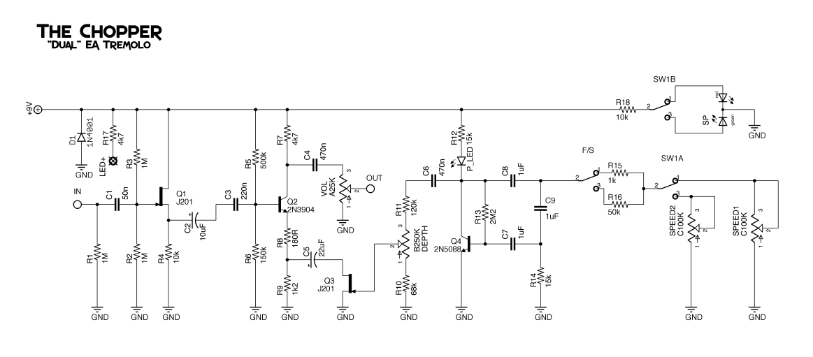
JHS Honeycomb Deluxe
Here's JHS' Honeycomb Deluxe tremolo. Or something close to it anyway. It's a modified EA Tremolo with an extra switch to control speed and a extra footswitch to switch between speed controls. Ian McDermott came up with a work-a-like for it, so this layout follows his schematic. This layout features board mounted pots and because of the 2nd footswitch I've laid it out for a 1590BB enclosure. Also this is laid out for film box caps like these, though others will work just fine.

Subscribe to:
Post Comments (Atom)
this one is verified.
ReplyDeleteI use 1mOm pot as Depth pot because 250k was not enough
and instead Q1 i put russian-made transistor кп501, with j201 as q1 i got weak and distorted signal
Cool. Thanks for the build report and for verifying!
DeleteThis comment has been removed by the author.
DeleteVerified? That layout to me did not work for me. What modification did you make?
DeleteThis comment has been removed by the author.
DeleteThis comment has been removed by the author.
ReplyDeletethe bypass footswitch as usual, for the speed switch you can use a dpdt.
Deletethe speed sw5 pad it is speed led +
cant make it work, i´ve tried different fets, j201,j112,2n5457, 2n5458. sound distored, and no tem at all. any idea?
ReplyDeletethanks!
It does not work. there is a clean sound and tremolo noise separately, but the guitar sound is not processed. I did twice from scratch
ReplyDelete10k resistor is lost, you should put 10k resistor at +10 uF capacitor and ground
DeleteI've made it and with tottaly same with in the layout.
ReplyDeleteI get the tremollo effect on output sound, but that sound have some noise, like "hiss" noise.
Anyone can help me to solve this noise problem?
I'm forget to tell one else, the gain/level volume is too low, and when I incrase the gain/level, the noice incrase too
DeleteI'm forget to tell one else, the gain/level volume is too low, and when I incrase the gain/level, the noice incrase too
DeleteOne switch selects between the two different speeds, and what about the other switch?
ReplyDeleteThanks
Both switches affect the speed. The footswitch selects between 2 different speed pots, the the toggle selects between 2 different speed modes for the overall effect. Much like the toggle switch in the Heartthrob Tremolo.
Deleteok, i get it now. Looking at the layout also helped... dughh
ReplyDeletethanks :)
still, it's a little strange why anyone would need this, because one of the switches only changes the min/max speed for the overall effect and that could be achieved with different pot values.
wouldn't it make more send to have different values for the speed pots, like speed 1 50K and speed 2 with 100k?
i know you didn't created this effect, i'm just sharing my thoughts
thanks again
I agree...
DeleteI don't understand the meaning of having two totally equal speed potentiometers. I don't see the difference between selecting one or the other, nor how they can affect the speed of different ways ...
On the other hand, although apparently it is verified, this scheme does not work for me (I have repeated it 3 times).
Ok guys, i think i know why so many people are saying that the layout is not working. You guys are probably not connecting the Rate Led, thinking it's just a "finishing looking good" thing. Nope, it HAS to be connected to the tremolo effect appears. I hope this helps some fellas who gave up on this pedal!
ReplyDeleteHi everobody
ReplyDeletewhat about pins 4 and 6 of the dpdt footswicht??
And (+) Leg of Speed Led??
I believe it's designed for the speed footswitch to have a bi-color LED to indicate which speed is selected. So the two anodes (+) would connect to lugs 4 and 6 of the DPDT footswitch, with the common cathode (-) going to ground.
DeleteThis comment has been removed by the author.
ReplyDeleteGuys! I found the way to make it works!
ReplyDelete1) 10k resistor between Q1 source is missing
2) Q4 transistor hFe must be over 500, I used BC548C rotated 180 degrees (hFe 560)
Works cool!
PS. Do not mark layouts verified when they are not! ;)
1) between Q1 source and ground
Deletethanks man!
DeleteI put the 10k resistor that is missing in layout, use BC549 hfe 502. I also lower the speed led resistor 10k to 2k4 to make the led brigther. For Q1 I tested several transistors trying lower the HISS and the 2sk117 works better.
Very nice pedal!
please reupload the schematic?
ReplyDelete