This is a library of perfboard and single-sided PCB effect layouts for guitar and bass. I'm not an electrical engineer by any stretch of the imagination, just a DIY'er who likes drawing layouts. It is meant for the hobbyist (so commercial use of any of these layout is not allowed without permission) and as a way to give back to the online DIY community.
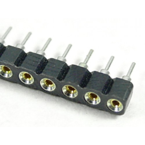
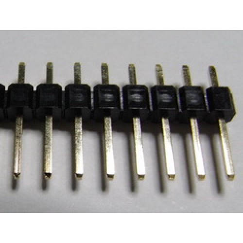
Got a request for the S2, but have been unable to track down a schematic for it, so here's the S1 in the meantime. It's an emulator/preamp of a Soldano tube amp, and like most amp emulators it uses JFET transistors. The original uses mostly SMD components with the exception of some capacitors, which is how they cram it into such a small box. As soon as I saw the schematic I figured this would be a good 1590BB project. Since it has 6 pots, I wanted to keep the offboard wiring at a minimum, so I made a daughter board to hard mount the pots using 16mm right angle PCB pots. This daughter board can then be attached to the mother board using sockets and pin headers, basically stacking the 2 boards. I would mount the sockets to the solder-side of the mother board, and the pin headers to the component-side of the daughter board (as the pots would be mounted on the solder-side of the daughter board). This might be a crazy idea, and if you opt to just use hook-up wire to connect the 2 boards, you won't need to wire the DB3 or DB6 connections, as they were added mostly for extra stability if you are using the socket and pin header approach.
Not included is the cab sim part of this pedal. If anyone is interested in a 2nd daughter board for this section, let me know and I'll draw it up and add it. Since the original mostly uses SMD parts, some of the members over on the FSB forum modified the circuit a bit to use more common through-hole parts. J201s are substituted for the original SMD 2SK208, and 1N4148 in place of BAT54 diodes. There are 2 caps that they weren't able to determine the value of. Based on the rest of the circuit, a good place to start would be 3.3µ for the first cap below Q1 (which I assume is an electrolytic based on the rest of the circuit), and 47nF for the cap between Q3 and Q4. Socket and experiment. Good luck!


