In an effort to make my own personal pedal board better, I'm building buffers at the input and output of my signal chain. As space and DC jacks are always a premium, I thought to build a dual buffer in a 1590A enclosure. The Klon Buffer is great and since it only uses half of a TL072, I figured I could just use the other half for the second buffer. It's a little tight depending on the jacks you use, but the board is small enough to mount vertically to an inside wall of a 1590A while the wall opposite can mount the 4 input/output jacks. Here's my
drilling template to better illustrate.

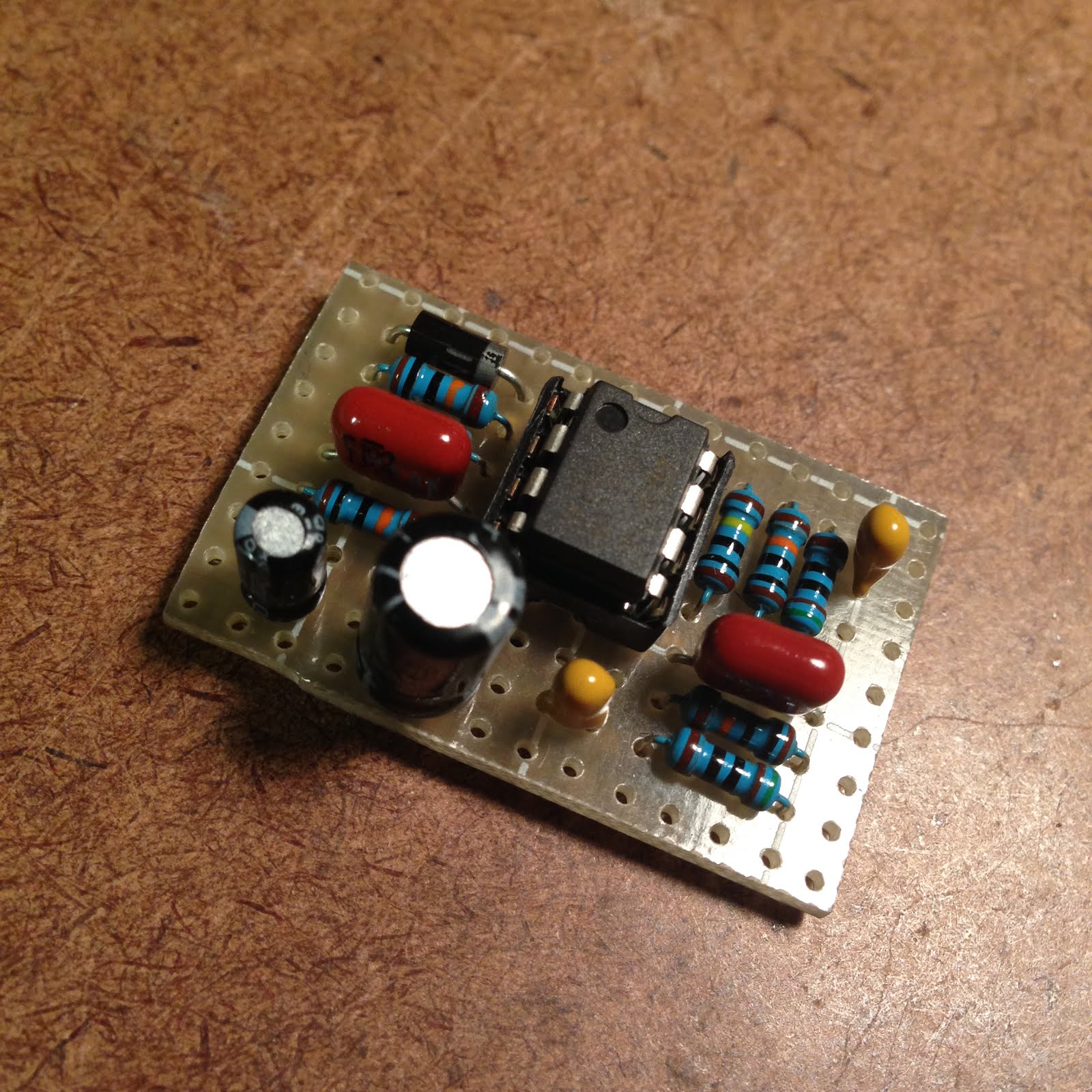
And here are a few pics of my build.


This is really cool!!!! Have you ever thought of doing this with the Pete Cornish buffer? That would really be cool also?
ReplyDeleteeducat me, this will be the 1st & last pedal/effect in a box?(patent pending)
ReplyDeletesomethhing like that, or not even close???
Exactly. You'd plug your guitar into the first input, then the first output would go to the rest of your pedal chain. Then plug your last pedal into the second input, and the second output would go to your amp.
DeleteGRACIAS!!!!!!!!!!!
DeleteIf I'm not mistaken, you only wire a ground cable to one of your jack plugs while the others are left unconnected. Am I right?
ReplyDeleteAnd since I have plenty of TL072s, I surely will build this to see what it could do to my sound.
awesome as usual, bro.
Because all 4 jacks' ground are connected through the aluminium case.
Deleteawesome. thanks Robert
Deletedone building this one, my guitar tone gets better
ReplyDeletethanks for this one
awesome as usual
nice idea bud
ReplyDeleteIf I'd like to make an Y splitter I only have to connect In1 and In2 together?
ReplyDeleteYeah, I think that'd work.
ReplyDeletejust curious... did you put an on/off switch for this one?
ReplyDeleteI did not. It's an always on thing for me.
Deletehello just finished the dual klon but i'm not happy for the sound !
ReplyDeleteIs the kind of the 2 1uf is important ? because I've put 2 1uf Electrolytic Capacitors type !! maybe it's for that ? are there tentanium ???
THX
Franck
I used tantalums in my build, but I would think the electros would be ok. You may just need to socket them and see what works better
Deleteok i'll look tomorrow and let you know ! just another question ! how pedals maximum you can chain ? because have a look on pedal bord please and tell what do you think ! is it a stupid idea ? How do you use with your dual klon buffer plugged ?
Deletehttp://www.hostingpics.net/album/FranckyDJ_f-275956.html
http://www.hostingpics.net/album/FranckyDJ_f-275971.html
You could put a buffer in the middle of your chain if you feel like there's any signal loss, but having this at the beginning and end of your chain should be ok I'd think.
Deleteok because it's incredible the lost of sound !!!! I shood and had to resolve why the sound is bad with my work…
DeleteThanks for your job ! its great ! i can participate for donate if you want !
It's the same with tantalum condenser !!! Don't know why ? :)
DeleteI've a sound with 3 db less and a little bit crunch ! i will change the tl072 ?
another question ! The dual klon must be use together or can be use separately ?
DeleteBecause when i plug the input of buffer 1 the sound go out of output buffer 2 ! Its strange no ?
Yeah they're meant to be used independently. And yeah, swap 072s. Weird that you're getting signal loss and distortion.
Deleteall my tl 72 are from tayda ! is there any equivalent ?
ReplyDeleteYou may just have one bad 072, so try another one. But any dual opamps should work (JRC4558, NE 5532, etc)
Deleteok ! many thanks for all !
ReplyDeleteLet you know when it will work !
"Weird that you're getting signal loss and distortion."
ReplyDeleteYes because it's a little layout and not complicated ! i have change the tl072 and Doesn't work !
I've try 4558 but it's not better ! Maybe a mistake with resistor ! I will see at night and tell you !
no really i can't and don't see nothing ! 100NF 0.1UF 100V 5% POLYESTER FILM BOX TYPE CAPACITOR is that right for the 100 nf ? I think should be ok !?
DeleteIsa you put 510 ohms resistor for the 560 … I imagine it's not important you had to have it on hand … I was happy to see any mistake in my mounting but quickly understood that no !
Healy i don't see ! condenser made ! can give me the voltage of each pin of the TL 072 ? Maybe a way …
i had your same problem with the pcb layout, i checked for cold solder joints and bridges, and those were probably the malfunctioning causes because it's now working. here are your working voltages:
Delete1 - 4,47
2 - 4,47
3 - 2,19
4 - 0
5 - 2,18
6 - 4,47
7 - 4,47
8 - 8,92
triple check everything, good luck
Ho ! thanks you very much ! i'm going to check it at night !
DeleteNo say what tell ! very things are ok on my work ! please ave a look in my aim ! i built a power supply who's integrate the dual clone … I don't the cables maybe, the 2 transformers about it ?
ReplyDeleteWhat's happened ? I don't see !
With corrections
ReplyDeletedon't know what tell ! every things are ok on my work ! please have a look on my alim ! i built a power supply who's integrate the dual clone … I don't know, the cables maybe, the 2 transformers around it ?
What's happened ? I don't see !
http://www.hostingpics.net/album/FranckyDJ_f-275971.html
ReplyDeleteinstead 100k, do yopu use 100k? (brown, black, orange)??
ReplyDeletesorry, instead 100k, do you use 10k? (brown, black orange)?
ReplyDeleteFor the Vref or the ones going to ground near the output?
Deleteboth!! i just finished but when i check the voltages, they are too low and the volume is so low. what can i do? =(
ReplyDeleteFor the Vref resistors you can use 2 of pretty much anything. When I built this I think I used 33k for there. For the 100k resistors going to ground near the output I'd stick with that value.
DeleteMy voltages are:
ReplyDelete1 - 1.37
2 - 1.37
3 - .90
4 - 0
5 - .90
6 - 1.37
7 - 1-37
8 - 9.20
These are pretty low. I think you need to double check your values and possibly just rebuild it. Correct voltages were posted above.
DeleteHello there! I have a simple question, sorry I'm pretty new at this, Are the jacks all stereo? or wich type of jacks I need? I was thinking about stereo for input and mono for output.
ReplyDeleteThank you.
You can use mono jacks if you're not using a battery. You really only need stereo jacks if your using a battery snap.
DeleteHi, can i use 1n4007 or 4001 instead of 5817? Thanks
ReplyDeleteYes, though there may be a little loss in voltage (like maybe half a volt). It won't hurt functionality though.
DeleteHello,
ReplyDeleteThe idea of this Klon Buffer is to used it in the beginning of the pedal board and in the end ? Because of that, you built it with 4 jacks ?
In 1 - from Guitar output to in1
Out 1 - from the out1 to the first pedal of the pedalboard
In 2 - from the last pedal of the pedalboard to in2
Out 2 - from the out2 to the amplifier
Am I right ?
Thank you very much!
Sorry,
DeleteYou've already answered !
"Exactly. You'd plug your guitar into the first input, then the first output would go to the rest of your pedal chain. Then plug your last pedal into the second input, and the second output would go to your amp."
I found this after having the same idea at work today and was looking for good buffer circuits to use. Funny. But I am now curious on how you would combine this with an ISP Decimator G String.
ReplyDeleteWhere can i found the pcb in the transfer image library?
ReplyDeleteThe Klon folder
DeleteHi!!
ReplyDeleteexcellent contribution I made the buffer but I would like to add a dpdt to turn it on and turn off the buffer. Could you guide me to the wiring? I do not know if I just have to wire the in1 and out1 to the dpdt. or they should be the in1 and in2 to the same pin of the dpdt as well as the out1 and out2. I hope to explain myself well.
Are you wanting 2 switches to turn each buffer on/off? In 1 and Out 1 are for the first buffer, and In 2 and Out 2 are for the second. Bypass wiring would be like this:
Deletehttp://fuzzcentral.ssguitar.com/faq/dpdtwiring.gif
thanks for answering so fast!
DeleteI was thinking of using a single dpdt for the two buffers, but I can't find information about how to connect the two buffers to a single dpdt. I do not have much space to put 2 dpdt.
Thanks for the help!
I don't think you'd be able to bypass both of them with one DPDT unless you go with a non-true-bypass.
DeleteThank you! I will try to put 2 dpdt then. Thanks for the help!
DeleteHelo Friends! Can I feed the buffer with 18v?
ReplyDeleteYes, just use appropriately rated caps.
DeleteOK! thank you very much!
DeleteThe lowest voltage value on the cover is 25v
Hello.
ReplyDeleteCan i use this for two pedal BLEND???? circuit????
i like your idea very much. i would also build this buffer but i need this circuit inverted on both outputs. What i have to do. Could you help me with this? Thank you for your help. Marcel.
ReplyDeleteGreat buffer, love how it keeps the signal pretty much untouched !
ReplyDeleteNow, can I just tie it's inputs and use it as a Mono to Stereo converter/buffer ?
Thanks
Yes you can. Done it myself in fact
DeleteI had the same idea. Can I join the two inputs with a jumper?
DeleteThankss for this amazing site man!
Exactly
DeleteWhats that do?
DeleteDo you have the schematic for this circuit? I have a dual effect build that both of the effects are in the same board and I need output buffers for both, so this would be the perfect solution, but I need the schematic so I can take off the reverse polarity protection and power filtering (which are already present in my effects' circuits) and fit it into my board. Thank you very much! :)
ReplyDeleteHello. If i want a 100 ohm output, wich resistors i have to change on the circuit? thank you
ReplyDeleteHola! Acabo de terminar de hacer el circuito, y tengo una sensible perdida de ganancia y de brillo. Probe los 2 buffer y en los 2 tuve el mismo problema. Exactamente el mismo.
ReplyDeleteAl ver la foto noto una sensible difernecia entre los valores expresados en los componentes y los valores que puedo ver en la foto.
Esto es, donde en el plano dice 1 Megaohm, en la foto veo 100k, y donde dice 100 kohm, en lo foto veo 10k.
Saludo!
Hola! Estuve equivocado respecto a los valores de las resistencias. Los vaores son correctos. Son resistencias de 5 bandas que en mi epoca de tecnico no existian...
ReplyDeleteTuve un problema con el valor del capacitor de 47uf, le puse x 25 volts y no funcionaba correctamente. Ahora le puse por 63v y anda perfecto!
Gracias.
Thanks works great (as usual). I just have to work out how to bypass it with 2 switches. :)
ReplyDeleteHi maestro..
ReplyDeleteCan I use this as a splitter?
Sure. Just connect the input pads together.
DeleteThank you very much.. You're the best
DeleteThis comment has been removed by the author.
ReplyDeleteHello, friend, I need your advice. I get audible distortions during a strong attack on the country, it seems to me that the buffer gets overloaded (my pickup is passive).
ReplyDeleteI adding a pot at the beginning of the buffer to attenuate the signal. And it helped, the distortion disappeared, but at the same time I lost the high frequencies.
I tried experimenting with various capacitors and resistors, reassembled the circuit several times and still get an overload((((
How else can buffer overload be eliminated without a pot?
could my problem be due to 12 volts, of power supply, instead of 9? Or maybe it's not high-quality tl072 (I tried 3 from one seller)
ReplyDelete