

Monday, February 1, 2016
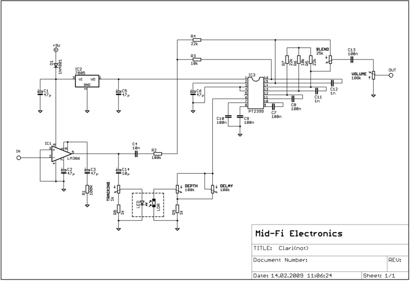
Mid-Fi Electronics Clari(not)
Here's the Clari(not) from Mid-Fi. It's a delay/vibrato/fuzz... thing that's pretty cool, and the sibling of the Pitch Pirate Deluxe. It uses an LM386 amplifier that pushes a fairly standard PT2399 delay and an optical vibrato. I've laid it out for on-board pots mounted from the solder-side and you should be able to squeeze it in a 1590B. Schematic can be found here.

Subscribe to:
Post Comments (Atom)
1M dark LDR...?
ReplyDeleteThat's a good place to start. You'll probably want to socket it in case it needs any tweaking.
DeleteWoops something went wrong there. Anyway, I wanted to say that out of all the PCB manufacturing guys your circuits most definitely have the coolest names! And the circuits are great too ofcourse ;) Keep up the good work!
ReplyDeleteAndrew | www.nexpcb.com
Great job for publishing such a beneficial web site. Your web log isn’t only useful but it is additionally really creative too.
ReplyDeleteused test equipment
anyone made this? ;) what ldr value did you use?
ReplyDeleteLDR - what is this?
ReplyDeleteLight Detecting Resistor or a photoresistor
DeleteThank u!
DeleteHello!
ReplyDeleteI just finished this project, great pedal!
I find two mods, that make sound better:
- replace cap between 9-10 legs of 2399 from 100nF to 680nF for more repeats
- replace 1K LED resistor to 2,7K get more range of vibrato
- yes, socket for LDR-LED is good
And I have one question: how add control pot for fuzz?
I found a 2k linear pot (wired as a variable resistor) between pins 1 and 8 on the LM386 works great.
DeleteThanx! Its helps, but some fuzz still present on low strings, I think it may be from 2399 or one of the caps...
Deletewhy I have a fuzz sound all the time in effect mode? I did that schematic like is in this page. Any solution? Thank u!
ReplyDeleteThis comment has been removed by the author.
DeleteI also have a fuzz i dont know why
DeleteHas this been verified?
ReplyDeleteNot to my knowledge
DeleteYes, verified
Deleteverified from brazil! this layout have some fuzz on sound, in the next that i build i will try cutting the trace coming off of pin 1 of the LM386. works great
DeleteHello everyone here
ReplyDeleteThen here, I built the pedal with some modifications suggested above -
Hello everyone here
Then here, I built the pedal with some modifications above. I used Panasonic FC and Wima MKP for the capacitors. Good sound! I can now compare the Clarinot with an original Seppuku Kassette. My Clarinot sound full, heavy but sweet with good bass. Kassette is more harsh. Maybe it's because Kassette is made from fucking cheap composants, i dont know. Ok ok.
I have a question : are the three pots "depth", "delay" and tracking" in the good sens ? They look inverted, no ?
Just completed mine.
ReplyDeleteI used an LDR that was sold by an aliexpress vendor as 1M but i haven't measured 1m from one of them even completely covered?
For the LED I used an old Agilent ultra-bright red bordering on orange. DOT rated for signal light use. I don't remember much about the specs, bought them a long time ago, but i think they have a very narrow viewing angle. Vf is 1.83ish.
Delay knob seems to work backwards (clockwise makes it faster).
I added a switch to toggle the fuzz but now that i think about it, I have some B5K pots with integral normally-off switch. I might see what that can do for me.
I didn't do any of the other mods but i might go back in and try them.
Thanks very much!
Please help!!!
ReplyDeleteI have fuzz sound
I want clean sound
Sorry my english very bad)
Try cutting the trace coming off of pin 1 of the LM386
Deletehello guys. i have a little question about this one. built it yesterday and it is "running" but my led, from the ldr, is not lighting up. i tested the led and i'm shure it is ok. mesured some values and i have no voltage on the anode pin of the led. its not supposed that the led receives voltage? in my newbbie mind, the effect to fully function, the led should blink and the tracking pot should control the peed of the bliking... i'm i wrong??
ReplyDeleteThis comment has been removed by the author.
Deletemilubit did you ever get this part figured out? thanks trader
Deleteto take off the fuzz i have isolated the pin 8 of the LM386; no more fuzz, but have some "overdrive" that i belive become of the pin 1, but i liked of this way
ReplyDeleteI Just finished, works, but not like I spected, Will try different Led and ldr.
ReplyDeleteHi, how to make the clean version with a "Feedback" knob please ?
ReplyDeletetake ideas from pedal pirate pitch deluxe (mid-fi). It´s similar and have all controls; you can make a hybrid
Deleteoh yes thank you
DeleteThis comment has been removed by the author.
ReplyDeleteCan't speak much to the LDR, but for sockets I use these for everything:
Deletehttps://www.taydaelectronics.com/30-pin-dip-sip-ic-sockets-adaptor-solder-type.html
This comment has been removed by the author.
DeleteThey're too short to work on a breadboard and unnecessary there. But yes, you can cut them off of the larger strip with a pair of snips.
DeleteThis comment has been removed by the author.
ReplyDeleteWhy is there no current limiting for the LED?
ReplyDeleteI put a LDR betwenn Pin 8 and 1 of Lm386 and 5k (I guess 1k -5k) Potentiometer Lug1 and 2 in parallel with LDR instead of the fuzzlift switch. Now it fuzzes when the string of the guitar or kalimba pushed harder. LED parallel with the other one. I use a red one.
ReplyDelete