

Friday, February 19, 2016
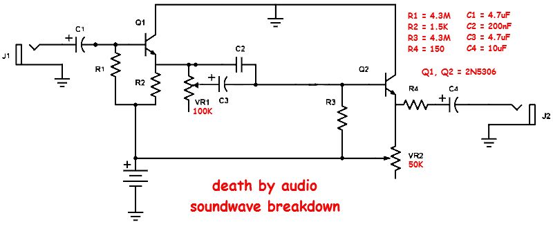
Death by Audio Soundwave Breakdown 1
Happy Fuzz Friday, everybody. Ranjam over on FSB traced an early DBA Soundwave Breakdown (serial number 4) which it's different than the current model. The unit he traced didn't have the trimmers later units did. Don't know the original value of those trimmers, but 50-100k is a good starting point. Those trimmers control the input signal (the left one) and the output volume (the right one). True to DBA form, this is a bit of a weird circuit with the NPN darlington transistors flipped around from usual (emitter to voltage instead of ground). Schematic can be found here. Should be able to squeeze it into a 1590a.

Subscribe to:
Post Comments (Atom)
how about a layout for the Brunetti Mercury? http://freestompboxes.org/download/file.php?id=22549
ReplyDeletecan you do a layout for this pedal? http://www.davidrolo.com/effects/giant-hogweed/
ReplyDeletelooks pretty good
What's the go with the pinouts on the transistors? Great work by the way!
ReplyDeleteThe pinout is BCE, so the one on the left is correct. Must have forgotten to change the one on the right.
DeleteThanks!
Deletehi
ReplyDeletewould you have soundclips of this early version of the circuit?
and would you have a schematic of the 6-transistor version?
i'm being really curious about this, i can't see any common point with the later version...
cheers
frances
The video above I believe is an early 2-transistor version. The schematic for which can be found here:
Deletehttp://freestompboxes.org/viewtopic.php?f=7&t=27423&p=257266&hilit=death+by+audio#p257266
The newer 6 transistor version I've also laid out and I like the the schem for it in the post:
https://effectslayouts.blogspot.com/2016/02/death-by-audio-soundwave-breakdown-2.html
There doesn't seem to be much in common between the two circuits. DBA just seems to have reused the name for a circuit they liked better.
thanks for the answer!
Deletei've already seen this video above, it is for the later version, they mention the volume trim pot which is not in the 2-transistor verion.
thanks for the links!
do you know if some of the transistors need to be matched, or selected for specific gain factor?
I don't know that off the top of my head, but it might be in the FSB threads. Lots of info over there!
ReplyDeletethanks, i'll go check that there!!
DeleteHi, built this today and dosent work. Any help i have checked my solder lines etc.
ReplyDeleteI'm triying this rare one.
ReplyDeleteNo succes at all.
Both transistors BCE (collectors to ground).
I used KSP13 (MPSA13), and MPSA29 (Hfe around 10.000).
Nothing happen.
When Bias is fully closed (no k's at all), the Collector of Q2 eat a LOT!.
Any idea?
Thanks!
There's a reason a lot of early DBA designs aren't in production anymore. I think this one, much like the original Fuzz War, was super hard to build consistently. The circuit may only work with the right transistors or even a certain manufacturer's transistor (that seems to have been the case with the original Fuzz War). This might be a good candidate to mess with and modify on a breadboard before committing parts to a circuit board.
DeleteThat's right
DeleteMore if I haven't the right transistors, that's very special.
The closest specimen NPN and Darlington that I found is the MPSA29.
What you suggest to tweak ??
Really, I'd just socket and try anything and everything I had on hand.
DeleteI just tried this one on the breadboard with Tayda 2N5306's and though I would share my results here.
ReplyDeleteWith the transistors oriented as per the schematic, I got barely any sound through. After flipping the emitters and collectors to the conventional orientation, the circuit produced a heavily gated and glitchy fuzz. Even putting a dimed-out LPB-2 in front did not overcome the gate effect. The bias pot was not much help, but changing the 1k5 resistor to 10k made the circuit a little more predictable. Even so, the effect was too glitchy and chaotic to be useful for me.
I just built one of these on perf, replacing the darlingtons with SC945's (regular BJT's with ECB pinout) with an Hfe of about 350.
ReplyDeleteWhile my build works, it sounds drastically different from the one in the demo. I ended up with a mild fuzz with a soft sound, in terms of both treble and attack. Rather than being gated, mine had pretty good guitar-volume clean up.