This is a library of perfboard and single-sided PCB effect layouts for guitar and bass. I'm not an electrical engineer by any stretch of the imagination, just a DIY'er who likes drawing layouts. It is meant for the hobbyist (so commercial use of any of these layout is not allowed without permission) and as a way to give back to the online DIY community.
Showing posts with label Utility. Show all posts

Tuesday, October 18, 2022

Boss SG-1 Slow Gear

 The Slow Gear emulates a guitarist riding the volume pot or a volume pedal, creating a swell effect. This will fit comfortably in a 1590B or 125B, though with the 1590B you'll probably want to wire the pots off board or use long-leg right angle pots mounted on the component side. Here's the schematic for reference.


Tuesday, October 5, 2021

Stompbox Converter

 Had a couple questions about stompbox use with line level, so I drew up this. This allows you to drop the line level signal down to instrument level, send it out to whichever stompboxes you want to use, then back and amplified back up to line level. Schematic and discussion here. Made two versions, one that could be run off typical +9v pedal power, and another for bi-polar 12v supply used in Eurorack synths, so you can build it either in pedal form or Eurorack module form.


Monday, February 22, 2021

Bomtempo

 Just stumbled across this on FSB. It's a tap tempo + modulation add on for PT2399 delays designed by Electric Canary. It is digital so you'll either need to buy a pre-programed chipset or burn the code onto the chips yourself. Lots of off board wiring with this, but it's probably worth if you have a favorite PT2399 delay you want to take to the next level. Check out their site for more info, schematic and the code.


Thursday, August 1, 2019

Fulltone OCB

What's the OCB you ask? It's the bypass buffer circuit from the new version of Fulltone's OCD. It allows you to switch between regular true bypass and buffered bypass. There are 2 versions: The first (smaller) inverts the phase of your audio signal when engaged (in bypass mode phase isn't inverted). The second (larger) adds an extra inverting transistor stage so that the phase of the output signal is the same as the signal coming in. If you've built an earlier version of the OCD in the past, you can add the 2nd board to make it into the newer version.


Tuesday, May 28, 2019

Bass Direct Box

Got a request for the DI portion of the Hartke LH1000 bass amp. This is more or less that, but with a simplified power section. In the amp this runs off a bipolar 15 volt supply, but I would think it would also work with regular 9 volt supply. There's not an unbalanced output, but if you need to add that you can probably add it off pin 3 of the XLR. Schematic for reference.

Tuesday, May 7, 2019

Baja Reactor

This one was requested ages ago and I got halfway through laying it out, and then promptly forgot about it. It's a power amp/speaker cabinet simulator, emulating a SLO power amp and a couple different speaker cabinets based on the value used for CX (see schematic for values). This layout follows the Rev4 schematic from the thread here on FSB.

Tuesday, February 19, 2019

Inverting Phase Buffer

Got a request for a dual buffer that inverted the phase of the signal. Found this post from Parasit Studio and used it for the basis of this design. I added polarity protection, power filter cap, and output caps. You can use either dedicated jacks for the in phase and inverted phase outputs, or use a SPDT toggle connected to a single jack and use it to select between the two outputs. (In phase output pad to lug 1, output jack to lug 2, inverted phase output pad to lug 3.) Should prove to be a handy utility. Single and dual versions below.


Tuesday, November 6, 2018

Demedash Effects Incandenza Bypass

The Incandenza Bypass is a simple, low parts count, relay-based  true bypass circuit designed by Steve Demedash. It uses a normally open momentary SPST footswitch triggering a simple 555-based flip flop circuit, triggering a non-latching DPDT footswitch. The layout below reflects the pinout of the either the Takamisawa NA5W-K or Omron G6S-2 relays. These are 2 relays I had in my parts stash that worked with the circuit when I breadboarded it and are both rated at 5v. Other non-latching relays can be used, but double check the pinouts and compare datasheets. Schematic can be found here.


Note: Send goes to the effect input, Return goes to the effect output, In goes to the input jack, and Out goes to the output jack.

Thursday, October 18, 2018

Hughes & Kettner Red Box Mk. II

Here's a nice utility box for home recording or even live application (if you've run into a sound guy who hates guitar amps 😠). It's a direct box but also a cab sim (4x12). It won't run off phantom power, so just power it with a 9v wall wart or a battery. Also, connected to the Speaker In pad should be another jack for "speaker through" (so you don't blow up your amp). Here's the schematic and original user manual for reference.


Update Nov. 15:
I removed the extra components for ground lift application as most reported it not working and they had better success with placing an on/off switch between XLR pin 1 and ground. YMMV

Tuesday, June 12, 2018

Optical Bypass

Here's another alternative to the 3PDT for bypass wiring. It's based on the method VooDoo Lab uses for bypass and uses a optocoupler to achieve true bypass using a DPDT. I've drawn up 2 different layouts for this: a standard perf/PCB layout, as well as another PCB I did in Eagle with the footswitch board mounted. There are extra pads so the compact or the larger DPDT footswitch can be used, as well as an extra pad for the resistor so 1/8th or 1/4th watt can be used.


Note, in the board mounted footswitch version In/Out pads refer to the jacks, and Send/Return refer to the effect in/out.

Thursday, April 19, 2018

Active Baxandall Network

Got a request for a Baxandall tone stack daughter board, (much like the Big Muff Tone Stack daughter board) and thought it was a great idea as it's a great tone control. The schematic for this came from this article, which is worth the read. I've laid it out two ways, one with board mounted pots, and one without that's a little more compact.


Note on the board mounted pots version the fill on the PCB is not ground.

Thursday, February 15, 2018

MultiCab Sim

Got a request for this one, designed by Daniel Schwartz. Seems to be a pretty versatile cabinet simulator. Might be handy to throw this in the same box as the Mini Amp from earlier this week. More info, schematic, etc here on DIYSB.


Also the next episode of the DIYLC tutorial is up on YouTube. Forgot to plug it in the post from Tuesday.


Tuesday, February 13, 2018

1 Watt Mini Amp

Here's a nice little solid state amp for headphone use or a small 4Ω speaker. Good candidate for a bench top amp for testing purposes. You can board mount the pot and it will fit in a 1590A just fine.

Tuesday, October 17, 2017

SMD to Through-Hole Conversion

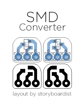
There are a lot of circuits (a lot) that use J201/2N5457 JFETs. Sadly, these components in the TO-92 package are out of production, and many of those that can be found online are either barely within spec or completely out of spec. So I thought it would be good to have a conversion board to use SMD transistors (that are current production and much more consistent) in through-hole layouts. Just solder some header pins to the holes of this board and you're good to go. I've also done a conversion board for BJTs, as some common through hole transistors are already being pulled from production.


If you don't feel like etching, you can pick these up in the store.

Wednesday, August 16, 2017

Simple CabSim

Came across this design in researching a different project and thought I'd draw it up. It uses 3 transistors and doesn't take up a lot of space, so you should be able to fit it in a 1590A or add it to another pedal. More info can be found here. Sounds like you can use pretty much any medium-high gain PNP/NPN pair for Q2-3 (2N5087/2N5088, BC560/BC550, etc).

Wednesday, July 12, 2017

iRig Preamp

Got several requests for this one. Basically, it's small preamp to plug into a mobile device for use with apps like iRig. Pretty simple circuit. Shouldn't be hard to fit in a 1590a or even smaller since you don't need to include a footswitch.

Wednesday, May 31, 2017

BMP Tone Stack

Had a few requests for adding a Big Muff tone stack to a few existing layouts. Call me lazy, but it's easier to draw this up than make a whole bunch of random alternate layouts. 😁  Anyway, it should be pretty handy. I've included a layout for just the tone stack, and one for the tone stack plus the gain recovery stage that typically follows the tone stack in a Big Muff. You can use different values for various responses (values listed in the image below).

Wednesday, March 1, 2017

Test Rig

Here's a couple test rigs you can use to test effects before boxing them up. They use the same board mounted jacks I used on the "board mounted everything" layouts I did at the beginning of the year. The first one is fairly simple, using a DPDT toggle to switch between the effect and bypass.


The second one is pretty much the same idea, but with a simple audio probe for debugging included. (Props to my buddy Cody for the idea) You can switch between test mode and debug mode with a SPDT on/on toggle.


Use sockets on the 5 pads in the middle so you can easily plug in wires from the effect you want to test. You can directly solder a wire to the Probe pad.

Wednesday, January 18, 2017

Ceriatone Klein-ulator

Got a request for this one. It's a effects loop buffer that's a solid-state version of the Dumbleator effects loop buffer. It's equipped with an internal charge pump that converts a +9v supply to +33v. Very useful for keeping your effects loop free from signal-loss. Since it runs at a much higher voltage than most effects, make sure your components are rated at at least 50v. Also the 10Ω resistor off the +9v pad should be 1/2 watt or higher.

Wednesday, November 30, 2016

PIC Relay Bypass

If you feel like getting into a bit of programing with your pedal building, this is probably a good place to start. The legwork was done and graciously shared by Coda Effects. It uses a PIC micro-controller to trigger a relay and LED indicator. To learn how to program the PIC12F675 read the original blog post on Coda Effects. Benoit has since updated the schematic, adding a photoFET to get rid of a pop that happened when triggered. So you'll need to read and use the code from this post as well. Thanks again to Benoit for sharing his code and all his hard work!


Update March 2, 2017: Benoit updated his schematic and code recently, so I've updated the layout to reflect that, as well as the hyperlinks above to the correct code.