

Monday, June 6, 2016
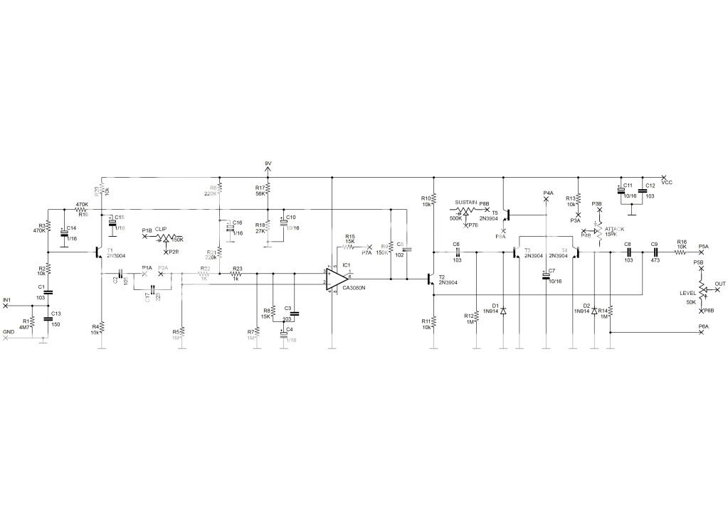
Keeley 4-Knob Compressor
The Keeley 4-Knob Compressor is a modified Ross Compressor and is highly regarded in the stompbox world. It's only down side is the use of the obsolete CA3080 chip. These can be hard to find and a little pricy. However if you're unable to find one, or unwilling to pay for one, use the LM13700 chip (which is 2 3080s in one) and this conversion daughter board. The schematic can be found here. If you have a hard time getting 150k pots, use a 250k pot with a 390k resistor in parallel (between lugs 1 and 3).

Subscribe to:
Post Comments (Atom)
Yaayyy! Another keeley!!
ReplyDeleteWhat happen to "recent comments" fiture of this blog? It seems no longer working.
Anyway, you are awesome as usual brother!
Yeah the code for that widget seems to be broken. *shrug*
Deleteone more, if I have to replace that B150Ks, what would you suggest?
DeleteRead the last sentence of the post
Deleteah... how could I missed that last sentence... my bad
Delete@Berkicau indonesian here, im newbs and have interest on building pedals, where should i contact you, i can't find any email or contact address. salam bang.
Deletecan i use this compressor with my active bass?
ReplyDeleteYeah, should be fine.
DeleteVerified! sustain is great) nice tapping :3
ReplyDeleteCool. Thanks for verifying.
Deletewhich layout did you follow? what transistors did you use?
Delete3904
DeleteGreat to see this one is verified. My build is 90% and still ongoing. Anyway, i replace the 150p ceramic with 100p and 47p in parrarel. Hope it would be fine
ReplyDeleteJust realize that the ATTACK on the perfboard is different to the pcb version. Which one should I stick with?
ReplyDeleteI'll fix that. The PCB side is correct.
DeleteHello! The solder side wiring pattern seems to be different from that of parts side around level pot connection point.For instance, 10nf cap connected to No3pin of 3080 is missing.Which should I stick with?
ReplyDeleteyea yea, I just realized it. perhaps this was the reason why my build didnt produce any sound..
DeleteBericau,
DeleteAfter my previous post, I figured out the issued solder-side also works.I have just confirmed it Sounds, not boxed yet though.Move the 10nFCap to below 15k resistor, and 1uF should be placed on the left side of the 15k connected to the ground via the hole on the left of 1M resistor.Minus pin to the ground.
Oh man, I must have had a massive brain fart. haha! It's fixed now and is consistent between the parts layout and the solder side. Sorry about that!
Delete@shimaneko, from what I read, you only move the components and don't change the way they are connected, am I right?
Deleteso my problem is likely bad component(s)..
UPDATE
ReplyDeletemy build is now working, but I really get fuzzier sound as I roll the SUSTAIN pot up.
for consideration, I use 100pF for the yellow cap instead of 150pF.
any suggestion to fix my build?
help me, anybody
most update
ReplyDeletemy build is now perfectly working
the problem was that my new strat's pickups were too close to string which made my gain was too loud
done this one
awesome like usual!
Could you please do the one with blend/ratio mod?
ReplyDeleteThank you very much bro
use a blender. I'm about to try it though...
Deletejust curious, if the output gain is too loud, will changing the 10k resistor solve the problem?
ReplyDeleteYeah increasing that resistor would lower the output, but so would turning down the level pot ;)
Delete
ReplyDeleteI finished my foot today , big pedal this , in place of the potentiometer 150k put a de200K with a 680K resistor between pin 1 and 3 , it was great
It's working but I don't have compression :/ Sustain works, Clipping works and Level works, but the Attack pot doesn't work. Any Idea? I put my multimeter in the 1 and 3 lug and gives me 150k, so I assume it's working outside de circuit.
ReplyDeleteNo encuentro el diodo 5817, reemplazo?
ReplyDelete4001/4007/4148 diodes
DeleteDiez puntos!!!
DeleteI got sound with the cable not plugged when i plug it i got no sound any ideas?
ReplyDeleteHi, this compressor is like keeley bassist?
ReplyDeleteNo. The Bassist is based around a THAT chip I believe. This is just a modified Ross Compressor.
DeleteWhat type of capacitor is big 1uF to clip 3?
ReplyDeletenon polar
DeleteIt's a box film type capacitor. I get them from Tayda.
DeleteWith respect to the 1uf non-polar capacitor, could I replace it with a polarized 1uf electrolytic capacitor or what replacement options would it have? regards
DeleteHi, can anybody help me?
ReplyDeleteIf I have sound signal at pins 2 and 3 of the IC which are the inputs of CA3080 then I should have had sound signal at pin 6 too, which is the out put of this IC right? And if there's no any sound at pin 6 then probably my CA3080 is bad, isn't it?
and I have something around 8V at pin 6
DeleteYeah I'd say either your chip is bad or you've got a short that's letting voltage from pin 7 bleed in.
DeleteI've checked It one more time, now I have 2.4 V at pin 6 and 0.1 V at pin 5 which is the amplifier bias, but right before 27k I have smth around 8 V, can't remember exactly now. But that's interesting, before 27k there are let's say 8V and right after 27k which connects to pin 5 I have 0.1. seems like the IC sucks all the current :D
Deletep.s at pin 7 I have 9V as it's supposed to be
DeleteSo, I've changed the CA3080, With the first one, I had no sound at all, with the second one a have a mega fuzz-distortion pedal ))). It's even more distorted than may Box of Rock.
DeleteSo.. again a bad IC or I have something wrong in my circuit?
Thanks.
Have you checked the rest of the build for faults? Run an audio probe through it any?
DeleteI have the same problem. Have you solved it?
DeleteSame here mega loud distortion pedal
DeleteThis comment has been removed by the author.
ReplyDeleteThis comment has been removed by the author.
ReplyDeleteThis is a really great pedal compressor. Thank you again, David. You, sir, are a legend! =)
ReplyDeleteOne thing I noticed in my build is that clipping control changes the tonality a bit - the lower it's set the less low end I get at the output (with overall output level matched). Is it normal for this ciruit?
Not sure. I haven't built it. You'd have to compare it to a demo.
Deleteit does like it supposed to be. so I believe that's normal
Deletethis is working already ?
ReplyDeleteI am the only one who got a lot of RF interference in this project even shielding the enclosure?
ReplyDeleteI get also a lot of RF interference. Have you found a solution?
DeleteIs there something that could be done to the uneven sustain I´m getting. Release is like in steps and not smooth at all. I tried matching the transistors (2n5088 hfe 470 +-5) but that did not help much. Also used 5% caps and 1% resistors. Anything else I could try?
ReplyDeleteHi guys, I have tried to build it two times and hadn't got any sound what so ever. Double checked everything. Could it be because of the used ic bought from aliexpress. It's CA3080E. Any suggestion what should i try to test? Thanks a lot. Paul
ReplyDeleteEverything woks ok, but im getting a little of highs loss, ive checked and rechecked values, is that normal? ive read that some comps make a bit of loss on the high end but on demos of this pedal desnt happen, any workaround?
ReplyDeleteSub for 1n5817?
ReplyDelete1N4001 will work
DeleteI had the distorted sound, then I change the IC and now I have low output. Can someone help me?
ReplyDeleteDebug IC. I had the same problem.
DeleteCA3080 or LM3080
1. NC
2. 4.6
3. 4.6
4. 0.0
5. 0.7
6. 2.7
7. 9.0
8. NC
Works for me!! great effect. cheers!
ReplyDeleteCan i sub 1uf box caps for 1 uf tantalums? Thanks!
ReplyDeleteHi guys, Is this verified? I have tried to build it two times and hadn't got compressor sound what so ever. They were like distortion sounds. Can somebody give me a hand?
ReplyDeleteIt is verified. It's very sensitive to the chip. If you're using a Chinese knock off chip it's not going to go well. Best to find a good RCA or Harris chip or use an LM13700 with the converter board.
DeleteI am very grateful, thank you. I was using CA3080EZ made by INTERSIL. Total of 7 of OP - AMP was tried from China and Japan, but everything was the same result. I'm looking for RCA or Harris chip, and I'm going to try it. Thanks!
DeleteI verified with the 'LM13700 to CA3080 Conversion Board' by NJM13600.
DeleteIt's a great sound. Many thanks.
Is there any chance to mod it to Compressor Plus? I mean to add single/humbucker switch ;)
ReplyDeleteWorks a treat thank you
ReplyDeleteIs there any modification of this pedal but for bass?
ReplyDeleteHi. My circuit works, however, I can not understand compression or attack. Checking the values on the IC pins, I found:
ReplyDeletepin 1: 0
pine 2: 3.61
pin 3: 3.61
4: 0 pin
pine 5: 2.23
pin 6: 2.22
pine 7: 8.46
pin 8: 0
The curious thing is that just after the diode (1n4007), the voltage dropped to 8.46v. Is that the problem?
Hello friends!
ReplyDeleteCan you tell me what type of capacitors are the ones we should use in this project?
Hola, no entiendo como debe ir la conexión del potenciómetro "LEVEL", la conexion dice del pin 1 y 3, por favor explicarme cómo iría conectado el potenciometro en LEVEL
ReplyDeleteHi people.
ReplyDeleteI finished mine. It seems perfect, but I noticed somethings weird. If someone could help...
First of all: I used LM3080N, 2n3904, metal fim resistors, ceramic, polyester and eletrolitic (polarized) capacitors.
Highs -- I get more highs than when bypassed. Where/what change to fix it? Any idea?
Saturation? -- Rolling up sustain, near of 95-97%, I get a kind of "explosion" and the sound is cutted off; and if clipping is full up (or down... right now I can't check), I lost the sound, staying just noises and a much lower signal.
Attack -- I don't know, but I can't notice difference rolling attack pot...
But the project is really cool! Thanks a lot!!
Built this using LM3080 and it works fine. The only issue I have is where can you get 150k linear pots? I've use 100k pots, however not sure whether 150k pots would be better.
ReplyDeleteOkay solved ... I read the last sentence of the post. :)
ReplyDeleteThis comment has been removed by the author.
ReplyDeleteVerified works good
ReplyDeleteIts working and 100% verified! Jun fr Philippines! Tnx guyz
ReplyDeleteDonde esta la salida de señal... NO la veo... Solo veo el In... and out??
ReplyDeleteApakah saya bisa menggunakan ic 13600
ReplyDeletecoba pakai LM13700, ada kok conversion board nya dari 3080 ke 13700.
DeleteThis comment has been removed by the author.
ReplyDelete