
There's also a fabricated version in the store, the LXII.

A couple notes:
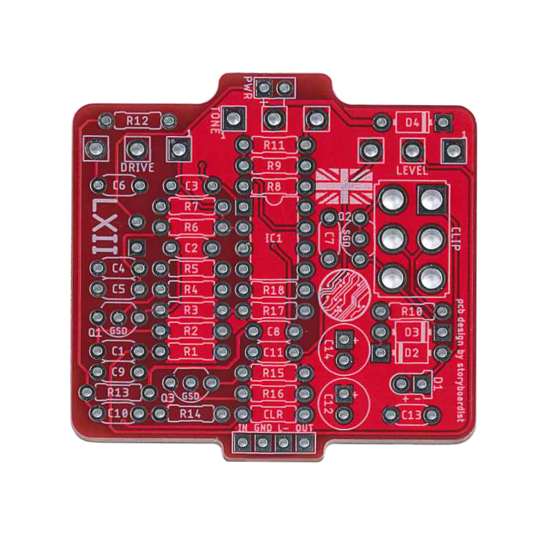
When I verified the fab'd version I didn't notice much difference tonally between the two clipping settings, so you may want to either leave it out or experiment with that section. I changed the value of the resistor from 9v to the drain of Q3 from 47k in the trace to 22k. Wouldn't bias properly otherwise. Also for the caps with questions marks in the layout above I used 10nF, except for the yellow cap to the right of the IC, which I used 100pF.
diodes 4148s reemplacement 4001 maybe sound different!! very good thnks so much!!! EXCELLENT
ReplyDeleteTwo SW1 pads?
ReplyDeleteTypo on my part. Fixed.
DeleteParabéns pelopotimo tebalhtr com os layouts, esteeja está verificanddo?
ReplyDeleteParabéns pelo otimo trabalho com os layouts, este ja está verificado?
ReplyDeleteAinda não ... apenas a placa fabricada foi verificada.
ReplyDeleteWorks great, I might mess a little with the tone cap on the top end but this does sound fantastic. Thanks for another great layout!
ReplyDeleteThanks for verifying, Bill!
Delete2N5458 does't work but J201 does. Very mysterious.. Anyway, thank you very much for sharing this one. I like it!
ReplyDeleteJust finished this one using 2n5457 transistors. Sounds great. I hear a very distinct difference with the clipping switch, well worth including it in my opinion.
ReplyDeletebut I get only clear sound, no distortion. What can it be...
ReplyDelete@Effects Layouts, the 100nF electro cap, is that 100nF or did you mean 100uF?
ReplyDeleteThat should be 100uF
DeleteCool thanks! Hey man, thanks for everything that you're doing here. Happy new year to you and your family.
DeleteAppreciate it! Happy new year!
DeleteAnyone built this one yet?
ReplyDeleteRead the comments? ;)
DeleteHaha yeah saw those. Tried to click on the link for the store but I guess the LXII is no longer available?
DeleteThe board didn't sell all that well, so I didn't keep it in stock :\
DeleteHi! I've just built it last night, but had no success in getting it to work right. As I didn't have the 2n5458, I used 2sk117, and I guess it's mostly why it's not working correctly - sounds very fuzzy and the signal is oscillating a bit. Perhaps it's something to do with biasing, but I'm not very confident with how to approach it. Also, I found this other layout on vero, and it ahs different components, such as additional diode, a 100uF cap... http://dirtboxlayouts.blogspot.com/2019/09/keeley-19621962x.html so I'm wondering which one's more precise... Any note you may share will be appreciated, thanks!
ReplyDeleteI went through and compared the two layout and aside from Fuzzhead simplifying some resistor values, I didn't see anything different. I think the 2SK117 has a different pinout than the 2N5458, so double check that. I could just be that the JFETs you used need to be biased differently than the original ones. You'll need to adjust the values of the resistors going from voltage to the collectors.
DeleteThis comment has been removed by the author.
DeleteThanks! Yup, I had to make adjustments considering those pinouts, plus I didn't catch it in the comments that the 100nF cap should be 100uF - that's why all crackling fuzz was happening and that was what confused me about the Fuzzhead'layut, plus he used 1n5817 diode... Anyway, it's a good one (a bit grittier than I imagined), and thanks for everything you're doing/done here - it's a place of wonders!
DeleteMine seems indifferent to removing the red diode or the 2n7000 transistor, although there is a difference between the switch positions... Checked all the paths - I'm clueless...
ReplyDelete