

Wednesday, July 5, 2017
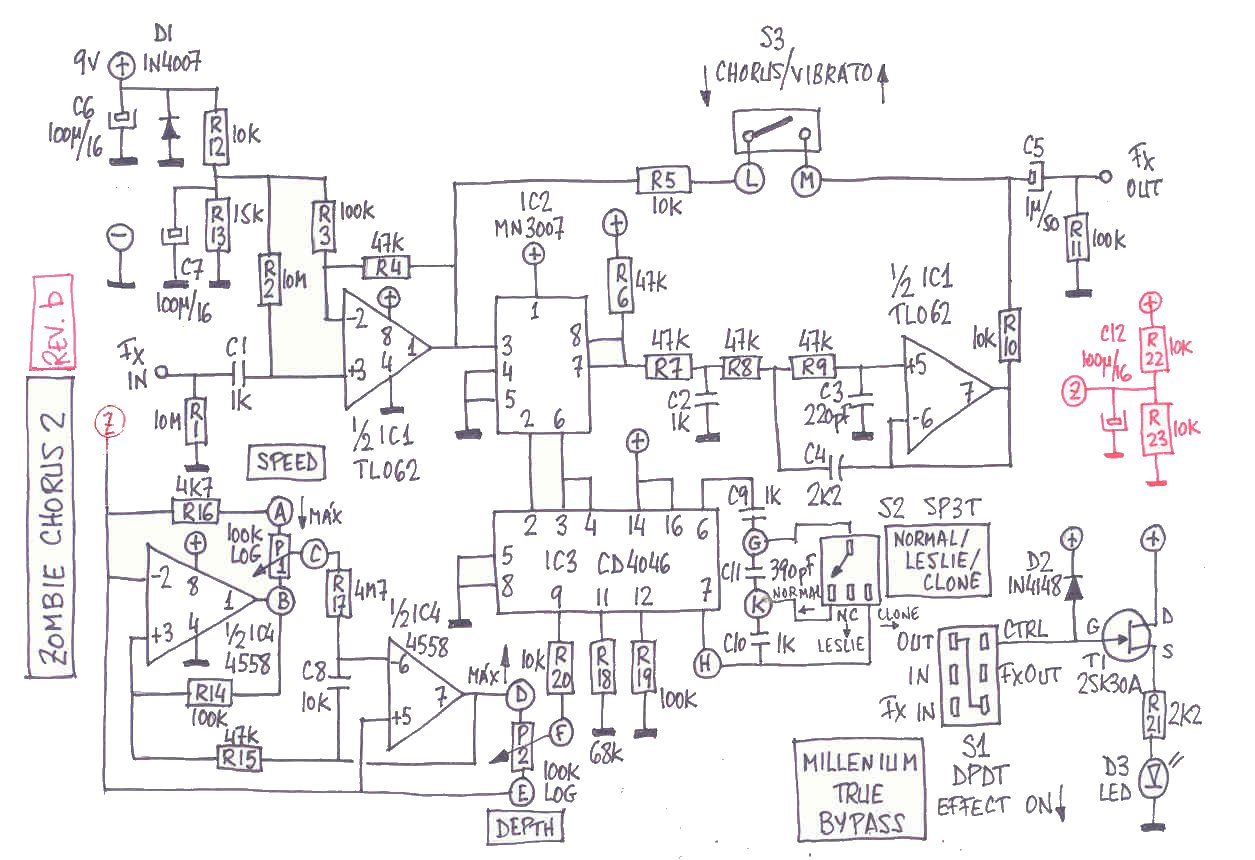
Zombie Chorus
Got a request for this one. This was originally designed by John Hollis and has since been modified by various folks in the DIY community. Like the latest version of the Little Angel chorus, it has a switch to do either vibrato or chorus tones. And the Mode switch allows for different speeds (Leslie, Normal, and Clone). Here's the schematic for reference.

Subscribe to:
Post Comments (Atom)
Beautiful layout, the big problem will be finding this MN3007 that is obsolete, any suggestions? Thank you
ReplyDeleteThey can still be found on ebay and other places online. As Mitsos says below, the MN3207 is a replacement, but doesn't have the same pinout.
Deletethe pinout is the same BUT the only difference is the voltage the mn3007 uses negative power and the mn3207 uses positive in 90% of the designs the mn3007 takes the positive but in reverse 9 vols goes to pin 1 thats the pinout difference although you cant say it pinout difference but power difference anyway
Deletea mn3207 zombie would be cool to have
LOL Love the zombie on the transfer board .. will do this. thanks.
ReplyDeletenice layout but why go with the mn3007 and not the mn3207 which is available everywhere and easier to obtain?
ReplyDeleteBecause the schematic called for a 3007. I'm not the circuit designer. And I've heard conflicting things about the 3207 with regards to noise levels.
Deletenope thats just myth i have used many times the mn3207 as an alternative for the mn3007 with some changes ofcourse without any noise just reduce the voltage a bit a aseries diode on the 9 volts and it would be awesome
Deletecool to share your conversion MN3207 to mn3007?
Deletebtw, i just found from ExpAnon :o
http://experimentalistsanonymous.com/diy/Schematics/Chorus/Zombie%20Chorus%20MN3207%20Based.jpg
The 3207 is a horrible chip - noisy and with significantly less headroom than the 3007. I have a few tubes of original Panasonic 3007s from the 1980s, and have been using them in some hand-built effects.
DeleteReally Really 3207 and a bit noisy, but would be an alternative, worth the pins being different
ReplyDeleteToo bad the pots are not board mounted but I guess it's not that easy.
ReplyDeleteThank you anyway for this layout!
is the layout available in the transfer library?
ReplyDeleteif yes where is it?
It's in the Hollis folder.
Deleteok i build this and to save a lot of trouble shooting for some people
ReplyDeletethe lfo section it misses two crusial parts and has one that in unnesecary
the 10k resistor below the 4M7 resistor must be replaced with a 10nf cap
and also the resistor that is missing is 100k from pin 1 to pin 3 of the lfo
and maybe the pots needs to be changed into linear i will report back when i test this one
i am also working on some mods on how to replace the mn3007 with a mn3207 that i will hapilly share
cheers from greece
the pots must be changed to 100k linear (b100k) it will give better control over the effect
DeleteThis comment has been removed by the author.
DeleteHi Mitsos,
DeleteCould you post a picture of the changes you made to your chorus to get it working? I think I have done the changes you mention, but mine still does not work. I get no sound when the pedal is active.
Thanks
same hare, it will be much appreciated if You can share somehow full working board.
DeleteI collected this scheme twice before reading the comments. Now it works correctly. There are two inaccuracies on the PCB - the 10k resistor under the 4M7 resistor is replaced with a 10 nF capacitor. Between the legs 1 and 3 of the chip 4558 soldered resistor 100 kOhm.
DeleteLove the sound of this pedal, but i prefer pcb with mounting potenciometers. Please with mounting pots. :(
ReplyDeletedid you build it with my corrections?
Deletealso if you build it where did you find the mn3007?
hello! i have the mn3007. How do you What went wrong when you built it that make you do those changes. Sorry my english ha ha
DeleteHello to everyone. I did what Mitsos Diaman says and works.
ReplyDeleteI did a bridge Vibe 2 to 1uf (out).
The effects sounds good, but there is a noise like mmmmmmm (think is ground).
Where did you put the 100k resistor thats needed between pin 1 and 3 of the LFO? Have any pictures?
DeleteThat noise is a non regulated 9v
ReplyDeleteHello, I think you forget the C8 from the schematic. This cap. is in parallel between the pin 6 and 7 of the 4558.
ReplyDeleteCould you check it ?
*forgot
DeleteThere is something still wrong in mine circuit. I checked voltage on each circuit and its correct however MN3007 just overheating and its probably already burned, no sound at all. Any Idea? I dont want to put another MN3007 and just bin it :/
ReplyDeleteHi. The Tl072 are valid for the op amps?
ReplyDeleteIt's a good replacement for the TL062, but the 4558 is used for the LFO, and I think the TL072 is harder to make oscillate. So I'd stick with a 4558.
DeleteI used TL062 instead 4558 and TL072 instead TL062. It works great.
DeleteOk. Thanks :)
ReplyDeleteHi everyone, I’ve built this but don’t seem to be getting any effected sound from it at all. I have replaced the 10k with a 10n cap but don’t know where the missing 100k resistor should go. I’m using a TL072 instead of a TL062 if that makes a difference?
ReplyDeleteAny help would be great.
Thanks
Can You fix the board for us please?
ReplyDeleteHi friends!!!! Amazing job you do!!
ReplyDeleteCan I use a CD4001 replacing the CD4046?
Regards!!!
No - the 4001 is just four gates, the 4046 is a PLL / VCO IC.
Deleteits amazing...great sound...thank man...
ReplyDeleteDoesn't work :/
ReplyDeleteMe to :(
DeleteI collected this scheme twice before reading the comments. Now it works correctly. There are two inaccuracies on the PCB - the 10k resistor under the 4M7 resistor is replaced with a 10 nF capacitor. Between the legs 1 and 3 of the chip 4558 soldered resistor 100 kOhm.
DeleteI built this one, but all i have Is clean sound. I made that corrections of 10 nf cap and 100k resistor but still clean sound. Dont know what more i have to do
ReplyDeleteI made it (10nF,100k included) but no dry signal. I saw the schematic and found the 1uF positive leg connected to vibe 2 ! Now it works fine. (but a bit noisy...)
ReplyDeleteThis comment has been removed by the author.
ReplyDeleteOne thing I came across was in the GuitarPBC Mini-Me chorus, he mentioned he isolated the ground of the clock to get rid of the clock noise. I did that on pin 4 of the 4558. Cut around the pin and put a separate ground wire from pin 4 to the jack ground. It worked great.
ReplyDeleteHi.
ReplyDeleteIf there a way to access to diylc file in order to correct the few things that were pointrd out in the comments, please ?
I'm also working on a modified version for 3207, I'll try and post it somewhere after I test it.
Thanks a lot !
Sure: https://www.dropbox.com/s/a5m5p0dwmmhewoj/Zombie%20Chorus.diy?dl=0
DeleteThanks a lot !
DeleteI did create it from scratch this morning though, but only to teach myself how to do it (brilliant tutorials on youtube btw).
I'll be able to triple check way easily now.
What do you think of the remarks that were made regarding the missing or wrong components ? Did you have the time to check them out ?
Thanks again !
This comment has been removed by the author.
DeleteThis comment has been removed by the author.
DeleteCud u share the fixed layout?
DeleteThis comment has been removed by the author.
ReplyDeleteHi !
ReplyDeleteI manage to succesfully built a MN3207 version :)
Is it alrigth if I put a link here, or would you be interested in having it, M. Effectslayouts ?
Thanks a lot, again !
Absolutely!
DeleteWell here it is (png I tried to do following your tutorials, but I didn't take the time to make the printable pcb part, sorry, and the diylc file as well)
Deletehttps://we.tl/t-rpVRYH0LnE
It'll be posted on the diystompboxes forums as well, if someone's looking for it.
Would you also be interested in the modifications/corrections I made to your layout (missing components from the Hollis schem), that I made before adapting it for a 3207 ?
Nice work. Yes mods/corrections would be appreciated
DeleteThis comment has been removed by the author.
DeleteThis comment has been removed by the author.
Delete(sorry, i corrected mistakes... 3 times)
DeleteThanks a lot !
The chip i used is a BL3207 and, even though I'm waiting for it to be in a enclosure to be sure of it, it's not noisy at all, even with a pretty good volume and extreme settings. I don't know if it's the biasing at 8.36V (roughly, tbh) but it's pretty "transparent".
Anyway here's the 3007 version with some changes to your layout :
https://i.postimg.cc/WjWrgDcL/Zombie-chorus-2b-fixed.png (it's on the diysb forum as well)
Here are the changes I made, mostly from the comments on this page and from the Geofex schematic (http://www.geofex.com/PCB_layouts/Layouts/zombie.pdf) :
- 10nf cap instead of the 10k resistor between pin 6 and 7 of the 4558 (C8 on the schem)
- 100k resistor added between pins 1 and 3 of the 4558 (R14 on the schem)
- 10k resistor changed to 15k between pin 2/5 of the 4558 and ground (in order to have the same "Vb" from the schem at both places it's used : TL62 and 4558. Maybe it's possible to only have one alternative voltage on the perfboard and PCB in order to save space, but I don't have the experience to rethink the whole thing, I'm afraid.
- two power filtering caps added between 9v and ground : a 100nf and a 47uf (C11 and C12 from the schem)
- i also rearranged things to move the vibe1/2 position to what seems to me like the correct position. Your layout isn't exactly what's on the pisotones schem, but in the end I'm not even sure if it does change something (since it's cutting the dry signal). If I ever built one again I'll probably put a pot in there instead of a switch (pin 1 instead of R5, pin 3 instead of R10 and pin 2 on the + of C5) in order to have a wet/dry mix control.
- of and fyi I didn't have a 390pf to put between mode 1 and mode 2 so I put a 200pf and a 170pf in parallel. It's almost identical to what's in the video, to my ears at least.
I think that's it, but I'll double check later.
Thanks again !
what would be the value of potentiometer in a wet/dry mix control if possible? tbanks ��
DeleteHi,
Delete10, 20, 50 or 100 would be fine I assume, linear taper.
Just remove resistors before the wet and dry signal meet, and put lug 1 on the dry (after the vibe/chorus switch), lug 3 on the wet and lug 2 going to the output cap before the output.
Hey Mathieu the mn3207 link expired, can u please repost it? Thanks
Delete@mathieu do you have pcb layout of it?
DeleteHi. No, sorry, only perfboard, and it's on diysb or fsb. If you're interested diyguitarpedal.au makes a really good one (that I tried). They solved all the classical problems of that circuit and it's compatible with 3007 or 3207.
DeleteWhere did u get bl3207?
DeleteI used fet3007 it was in local store mn3007 box.. but theres no chorus.can i used cd4046be. Do i need 4046ube or 4046be is fine?
Hi. No idea what a fet3007 is... are you sure it's a bbd chip ? Any 4046 will do imho.
DeleteAnd i found my 3207 in a crappy karaoke machine I got in a flea market, it had old dual and quad opamps in there as well.
DeleteAny crappy "audio" device that has a "echo" knob or setting seems to have a 3207/3102 circuit for a fixed delay.
The legend even says some old karaoke machine had SAD chips in there, but I never found any.
The 3207 versión is not longer available, could you please update the link. Thank you
Deletea 10k or 20k pot.. maybe, a noob guess..
ReplyDeleteHey what size enclosure does this best fit into? Does anyone know?
ReplyDelete125B
DeleteThank you!
ReplyDeleteZombie chorus! Yes this one for sure on the listbuilding!!
ReplyDeleteFor this one im gonna use mn3207 . A challenge for my tweaking instinct maybe...
ReplyDeleteI'll report whats the outcome maybe nxt week guyz.
The positive side of 1uf electro should be connected to the vibe sw 2 terminal as per schematics is concern and not directly to the output amp of tlo62. Cheers!
ReplyDeleteMn3207 works great!in the absence of mn3007 , mn3207 fits in zombie chorus!
ReplyDeletePin 4 guyz should be bias around 8.36 volts to get that nice sounding chorus.i hope this would help in anyway. Be sure to check the pos and neg pins of this chip .
Could somebody please post a fixed 3207 version? Thank you
ReplyDeleteIt's on diysb https://www.diystompboxes.com/smfforum/index.php?topic=123867.0
DeleteThank you, that is exactly what I was looking for.
DeleteHow do connect vibe 1, vibe 2, mode 1, mode2, n mode3 ? Thanks..
ReplyDeleteCheck the General Layout Notes tab for switch lug numbering.
Delete