
In my search for one that was fairly simple and wouldn't take up too much room in a pedal, I came across this article from a few years back by Paul in the Lab. It uses just 3 transistors, a momentary switch, and a DPCO-type relay. I've drawn his circuit up for use with a board mounted SPST momentary off/on footswitch (if you need a perf layout, check out this one over on lvlark's blog). You'll need a 5 volt Omron G6S-2 relay (I got mine here), and a lot of different transistors can be used. BC547 and 557s are called for in Paul's schematic, but 2N3904 and 3906s or similar can be used as well. Most SPST momentary switches I found had the solder lugs on the side, so the board has been laid out to fit vertically in a pedal enclosure. Everything is mounted to the circuit board on the component side and the board is small enough to fit in a 1590B.
Note:
This has been updated to reflect the discussion below.

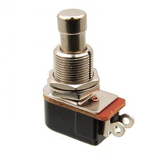
Here's how the switch should mount to the board.

we got some kind of mind meld going on? drew up the schem for this in eagle on friday
ReplyDeleteGreat minds, as they say... :D
DeleteVery nice! Just keep in mind that if you want to use your pedals with batteries, don't use this kind of relay switching, or you will run out of juice very fast!
ReplyDeleteWhat is this "battery" you speak of? ;) haha
Deletehttp://www.dv247.com/assets/products/215258_l.jpg :B these old fashioned and nasty things
Deleteit will work creating a true bypass looper?
ReplyDeleteI don't see why it wouldn't.
DeleteThis relay should work? http://www.victronics.cl/index.php?page=shop.product_details&flypage=flypage.tpl&product_id=11449&category_id=3070&keyword=dpdt&option=com_virtuemart&Itemid=1
ReplyDeleteNo. The spacing is too large and it's a 12v relay. You need a 5v or 9v.
DeleteThank you! Thank you! Thank you! Thank you!
ReplyDeleteHi, does the 5V relay, a latching or non-latching relay?
ReplyDeleteLatching
DeleteThe one you linked above is non-latching one(G6S-2). For the latching relay, the model no. is G6SU-2.
DeleteI reread Paul in the Lab's post and some of the comments there and the relay actually needs to be a non-latching. So the the relay I linked to above will work. Sorry about that.
DeleteYikes! I just ordered 5 G6SU-2 relays. Now what to do with them? I know, You could make another layout using latching relays!
DeleteWhat kind of switch? NO, NC?
ReplyDeleteNormally open
DeleteThanks for the reply. Great site BTW! Any chance you will be adding some 2 or 3 parallel loopers in the future?
DeleteHi, can I use this relay for this schematic? Many thanks! http://www.ebay.com/itm/NEW-HUIGANG-Relay-5V-PCB-HRS-Relay-HRS2H-S-DC5V-x-5pcs-/120853567051
ReplyDeleteThat one looks to be too big (size-wise). The pins are farther apart than what's laid out here. I verified this myself with the relays linked in the post above, so try and grab some of those. They're Omron G6S-2.
DeleteOh, okay, I will give it a shot. Thanks a lot!
DeleteHi, I've tried the relay from my link because omron relays are hard to find in my hometown, and it sucks. The LED turned on immediately when I plug the 9v, and nothing happens when I press the switch. I have one question about the omron g6s-2 relay and the relay from my link: do they work the same? This is the first time I'm using a relay and I have no idea what's going on. Thanks!
DeleteTheoretically, yes. The relays do the same thing. The differences come down to tolerances, the type of switch being triggered, pinout, etc. The switch you linked to appears to have a different pinout than the Omron G6S-2 the layout is designed for. If I'm reading the datasheet correctly the common pins are the top two pins (of the group of 6 pins below the relay coil pins) instead of the middle two pins like they are in the Omron. Switch those and it could work. Compare the datasheets and you'll see what I mean.
ReplyDeleteI would highly recommend doing some research on the subject. There is a wealth of information out there between forums, blogs, etc from smarter people than me.
Nice! I used the omron relay and the switch is working. There's problem though. When the led is turned off the effect is bypassed, but when it's on, there's no sound coming out. CMIIW, but the "board in" is the "send", and "board out" is the "return", right? Am I missing something? Oh, and is it normal when there's popping sound in audio when the switch engaged?
DeleteYou're correct re send/return. You might need to add a pull down resistor (1M or higher) from send to ground if your effect board doesn't have one. If you socketed your relay, try triggering it, then removing it. Put it back in place and see if LED comes on when it's in send mode.
DeleteI'm sorry but after many days of trying, there's no sound coming out from the send and return mode. Is there any special wiring for the jacks? I connect all the tips to the corresponding holes and the sleeve to the same ground.
DeleteI think this layout is actually for the G5V2 relays and not the G6SU ones. The common connections on the G6SU is the middle of the three pins (like on a regular DPDT) unlike the G5 relay which has the top of the three pins common.
Delete@Jonathan. My amendments to get this to work are as follows: https://67.media.tumblr.com/feeb2b7be41506b0b455ee55473e401a/tumblr_obtpcbES5n1qkzl6yo1_1280.png
DeleteThe blue line on the left image is a new jumper on the component side. I needed to drill the holes for each of these a little larger (1.2mm) to get the jumper and the relay leads to fit.
The red lines are cuts on the traces. Check these without the relay installed :)
The blue lines on the right side are little bits of wire i added after all components were installed to act as new traces. Do this, and your effect should now work. A bit of a ghetto solution if you can't be bothered getting new relays like me. :)))
Cheers gang.
is this true bypass?
ReplyDeleteYeh boi.
Delete100% working?
DeleteYou gotta ensure you have the correct relay.
DeleteHas anybody verified this with any of the relays mentioned? Seems like were down to modifying the layout with cut traces and new jumpers. It would be nice to know which relay is correct, or if the layout needs to be corrected.
ReplyDeleteCompare the switching schematic on this: https://www.omron.com/ecb/products/pdf/en-g5v2.pdf
Deleteto this: http://www.omron.com/ecb/products/pdf/en-g6s.pdf
The layout shown above is actually for the first switching layout. The relay switching itself works perfectly on mine, but the pinout is different so it won't pass effected signal. The size of the G5 is too big for this layout though I think.
You guys are making this harder than it has to be. Get the relays I posted a link to. They're non-latching G6S-2. They work fine. If you can't find that relay, I get it. Try the 555 Relay layout or one of the other relay layouts that are on the web (you won't hurt my feelings if you make someone else's layout haha). But unless you really know what you're doing with relays (or are prepared to research and learn a bunch about them), don't try and modify the layout to work with other relays–you'll just frustrate yourself.
ReplyDeleteI apologize if this comes across the wrong way. It's not my intention. The information in this is contradicting and confusing if your're reading through this for the first time. Luckily I've been following this now for sometime.
DeleteInitially I purchased 5 of the G6SU-2 as you suggested in the description of the layout. Which still suggests the G6SU-2 btw... Reading further in the comments I see it's actually supposed to be a G6S-2 which is a different relay. No big deal, I've now purchased 5 of the G6S-2 relay. I built 3 of these layouts now and have a similar issue as others having trouble that it does not pass the effected signal, only the bypassed signal.
I'm not trying to sound like a jerk. I appreciate the work you put into this providing all these great layouts for us. This is the first one that has given me any grief. But, after having trouble with this particular layout it brought me to ask the question if anyone has actually had this work with the relay's mentioned. I'm not interested in butchering layouts...
One other thing I noticed. The image of the layout above is actually different than the image in the transfer image library.
Thanks again. Really! Just trying to get things straightened out.
this should work?
Deletehttp://ph.rs-online.com/web/p/non-latching-relays/6839845/
This is what I purchased...
Deletehttp://ca.mouser.com/ProductDetail/Omron-Electronics/G6S-2-DC5/?qs=sGAEpiMZZMs3UE%252bXNiFaVHZYBcGbFFQb0n1t1eLRS2Y%3d
Heh I bought the exact relay you linked to (the G6S2) and it has a weird pinout. In my pinout, the ground and the input jack pin (the one linked on the right side) are the common connection which switches between the board + output pin, and the bottom left input jack and board out pin.
DeleteWhen the switch is in the top position, the board is grounded, and the input jack and output jack are connected. This is why bypass works.
When the switch is in the bottom position, the input jack is grounded which gives no signal. The input jack is also connected to board out.
Unless there are different models of G6S2, the one linked won't function correctly.
That's exactly what's happening. The board when engaged becomes grounded. The only difference I've noticed between the G6S-2 are mounting options. SMD, through hole etc... Otherwise they are the same relay.
DeleteDisregard the comment about the different images. I see it's been updated. The extra jumper for 9v to the relay isn't required anymore.
ReplyDeletethis should work?
ReplyDeletehttp://ph.rs-online.com/web/p/non-latching-relays/6839845/
That's the 9v version. It might work, but I know the 5v one will trigger with this circuit.
DeleteOk guys, I've gone back over the layout and my build and you're right. The relay triggers (which was the main thing I was concerned with when I originally built it) but I had the pinout mixed up with a different relay I intended to use originally (same one that lvlark used his his version of this). I've updated the layout and transfer pdf. Sorry about all the confusion.
ReplyDeleteNo problem! Thanks for the update!! :)
DeleteWoohoo!
DeleteHello,
ReplyDeletePlease change to Omron G5V-2 on the PCB layout :)
It doesn't use the G5, it uses the G6S-2.
DeleteOK! I built this and boxed it with the Cornish SS2 layout and it WORKS. Nice and quiet like it should be. Consider this verified!
ReplyDeleteThanks again for the new layout!
That was fast! Thanks!
DeleteDo you have scheme? I built and only work in bypass. No effect sign.
DeleteLink to the schem is in the post above.
DeleteWhere? The paul web is down and tagboard don't post the scheme
DeleteTry it again. Looks like he ported his blog or something. Should work now.
Deletei build this using 9v G6s2 non latching its working but experience some ticks on and off any solution to this problem?
ReplyDeleteI just built one of these to go along with my green Russian muff with mids. Works fantastically. thanks
ReplyDeletewhat relay do you use ? good for you then
ReplyDeleteIt might work. This circuit seems to be hit or miss. But that relay seems to match the specs necessary.
ReplyDeleteI've tried to good routing pcb's to mount a switch like this with no luck. I'm a little confused on the process. would a dremel work?
ReplyDeleteDrill holes at the top and bottom of the slots, then open up in between with the dremel.
DeleteThanks!
DeleteHey, could I use a SPDT switch instead of a SPST? and how? the SPDT that I have is this: (https://www.amplifiedparts.com/sites/default/files/uc_products/p-h492.png)
ReplyDeleteHello again, i got some NAW5-K relays, and i checked pinout, same as the G6S-2-5V so it will work on this circuit. I have other question : i think the coil of the relay needs a flyback diode. I will try them all and give feedback . Also i thought it would be a good idea to make 12mm hole on the center of the pcb to let switches go trough and take less space so we can squeze more stuff, i will use my noob eagle skills to make it happen and send it to you if i get lucky. Thank you again!
ReplyDeleteUpdate: NAW5-K works, but sometimes I get misclick, I think it's not about the relay, I increased the cap and no misclicks
ReplyDeleteTrying to use your layout for a flip-flop pedal and want to turn the switch into a 4PDT. Based off the limited research I have found online, can I use run another relay parallel with the original relay to make it act as a 4PDT instead of a DPDT? Obviously I need to create another layout, but would appreciate your thoughts.
ReplyDeleteYeah, that should work. Tho I would suggest using a different circuit to switch the relays, as this one has had mixed results. The 555 timer-based one works well.
DeleteI am assuming that you could wire two of these to one SPST to switch two effects with one stomp? Thinking about using this idea for a stereo rig to activate two different distortions.
ReplyDeleteI'd suggest using a DPDT momentary to do that. That way you can use different poles for each relay. Also, do yourself a favor and just use the Incandenza Bypass.
DeleteMakes sense, I will give it a go.
DeleteThanks!
the led is flashing for a moment and then goes dark.. is it because of the non-latch relay we are using ?
ReplyDeleteHi, can it works with mcb-s 205?
ReplyDeleteThanks
This comment has been removed by the author.
ReplyDeleteThis comment has been removed by the author.
ReplyDeleteThis comment has been removed by the author.
ReplyDeleteIs ivlark and urs layout schem is same?
ReplyDeleteHe says u can use 12v dpdt
If it is i want to try this with 12v. :)
hi, i have a pop in this circuit, i've used all the components in the layout, but i have a treble pop, like a tic, anyone knows whats happening? Thanks for Brazil!
ReplyDeleteI would highly recommend just doing the Incandenza bypass. I've never had an issue with it and I've built at least 10 pedals with it and haven't had an issue with it at all.
ReplyDeleteHi, does the right leg oh 10k resistor - (1k and 470k in front of Q2) should be left not connected from transistor side?
ReplyDeleteThere need to be diode across +- of relay coil i used 1N4148 and it work as charm. Before that i had problems with relay switched too fast or too slow... (it stayed on)
ReplyDelete